logo elektroda
logo elektroda
X
logo elektroda

[Solved] EARU EAKCB-EWE-M WiFi Module Identification and Pinout for Firmware Flashing

ProfAnderson 702 25
ADVERTISEMENT
  • #1 21584971
    ProfAnderson
    Level 4  
    I'm looking for help to identify the module and thus the pinout (for flashing) for the wifi module in a EARU EAKCB-EWE-M "circuit breaker" that I just bought off AliExpress
    https://www.aliexpress.com/item/1005006189189642.html

    ** Update: with wonderful help from forum members, the EAKCB-EWE-M circuit breaker and associated PTBLU-W wifi module are fairly well documented. Follow this link to get teardown info and pictures, pin out, and other details: https://www.elektroda.com/rtvforum/topic4129041.html#21598413 **

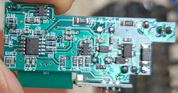
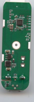
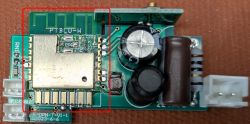
    I've verified that it works with ewelink so I'm hoping I can flash it with new firmware (e.g. OpenBK or Tasmota). I'm attaching pictures of the front and back of the circuit board containing the wifi module.

    FRONT of circuit board (Wifi module circled in red)
    EARU EAKCB-EWE-M WiFi Module Identification and Pinout for Firmware Flashing

    BACK of circuit board
    Front side of the EARU EAKCB-EWE-M automatic switch PCB with the WiFi module outlined in red.

    The only marking I see is "PTBLU-W" in the silkscreen and searching the web comes up empty. There are no markings on the RF shield no matter which angle I look at it. Based on a post I found, I was hoping it would be the PSF-B module mentioned in: https://www.elektroda.com/rtvforum/topic4068651.html but no such luck.

    I'd use a sonoff device, but they generally have a current limit around 20A or less (for a single channel); I need to monitor and control a higher current (30-35A for my EV) and this has a relay rated for 60A.

    Thanks in advance for any help you can offer.
  • ADVERTISEMENT
  • #2 21585083
    p.kaczmarek2
    Moderator Smart Home
    That's a very interesting module, I haven't seen it before. Would you be able to remove the metal shielding with hot air so we can check which chip is inside?
    Helpful post? Buy me a coffee.
  • #3 21585643
    ferbulous
    Level 18  
    Could be an esp32 (wroom-06)
    Looks like cbu, but it’s running ewelink firmware
  • ADVERTISEMENT
  • #4 21585648
    p.kaczmarek2
    Moderator Smart Home
    I would like to see firmware dump from that. It wasn't marked as Matter, was it? So it should not be protected...
    Helpful post? Buy me a coffee.
  • #5 21586371
    ProfAnderson
    Level 4  
    I don't have a hot-air tool to remove the metal shielding but I was able to bend back the top right corner. The chip is a BL602.

    I would be happy to post a dump of the code if I can get get it. To get the dump, I need to know pinout of the module. I noticed in another post there's a CBU module that has the same number of pins (7 pins on each side): https://www.elektroda.com/rtvforum/topic4000643.html Although it's not identical (the one in the post has circuitry for temperature, and it runs Tuya code), they may be similar enough to try connecting.

    I found a site with the pinout for the CBU - https://developer.tuya.com/en/docs/iot/cbu-module-datasheet?id=Ka07pykl5dk4u so I'll try and see if that pinout works.  By tracing the circuits on the back of the main PCB I can at least verify the +/- supply pins.

    Thanks again for all the replies so far. :-)
  • #6 21586404
    p.kaczmarek2
    Moderator Smart Home
    Please be careful with module pinouts, the best source is Tuya website, I've did a correction. See here:
    https://developer.tuya.com/en/docs/iot/cbu-module-datasheet?id=Ka07pykl5dk4u

    For BL602, see here: How to read and backup flash of BL602/BL702/etc device with BLDevCube? Burning tutorial, pinout
    Helpful post? Buy me a coffee.
  • Helpful post
    #7 21586742
    Daro1003
    Level 34  
    EARU has as you can see several models of these modules I practiced with a similar one. Today I have 3 pieces and they control the heaters work reliably on Tasmot.

    Link to my topic in the footer.
  • ADVERTISEMENT
  • #8 21587705
    ProfAnderson
    Level 4  
    @Daro1003 I'm very interested in any details about your modules and how you reflashed them. Your post says there is a link to your topic in the footer (of your post), but I don't see any footer or link? Can you try reposting to include the link? Thanks.

    Added after 1 [hours] 39 [minutes]:

    There is one question that blocks me from continuing. Flashing the BL602 requires 5 connections - VDD, GND, TX, RX, and BOOT. I can take a good guess for VDD, GND, TX, and RX by assuming my module is intended to be pin-compatible with the CBU module. But the CBU module actually uses the BK7231N and I don't see a BOOT pin on the BK7231N. So I don't know how to guess which is the BOOT pin for my module. I don't have the tools to unsolder the metal shield or remove the Wifi module from the main circuit board, so I can't try to follow the traces. So I don't know how to continue.

    Thanks for any suggestions or help.
  • #9 21587790
    p.kaczmarek2
    Moderator Smart Home
    The only efficient way is to desolder the metal shielding. If you don't want to desolder the metal shielding, then the only second option is to solder GND, 3.3V and then try guessing which pin is UART log TX (output) by touching each pin with USB to UART RX and observing Realterm/UART window and adjusting the baud rate. This way you may be able to get debug log output and then figure out which chip is it.
    Helpful post? Buy me a coffee.
  • #10 21588629
    ProfAnderson
    Level 4  
    I thought it would be a good idea to confirm that I can use the flashing tools successfully before experimenting with the new PTBLU-W module. I had a SM-028_V1.3 module with the same BL602L20 chip, so I practiced with that. After several hours, I have to admit I've gotten almost nowhere. The results seem almost random, and I have a very hard time consistently getting even the beginning of some good results. Some details are:
    - Using fully patched version of Win10
    - Using a 3.3V supply with >200mA capability (Boufallo specs say I shouldn't need more than 5-7mA while flashing)
    - Using a MAX3232 UART; spec sheet says max 230400 baud; I tried many different baud rates but mostly used 115200
    - I'm just trying to start by reading the chip ID, as suggested in one posting
    - I mostly used Boufallo Lab Dev Cube ver 1.9.0, but also tried ver 1.4.8, and command-line as well as GUI tools

    MOST of the time, I don't get the ack code (4f4b) so everything fails. :-(
    SOME times, but not often, I get the ack code, succeed in getting the chip ID, succeed in getting the segment data (10 parts), and then I fail to get any further through the process. This sequence is copied below.

    Since I *sometimes* get (partially) good results, it makes me think that the practice BL602L20 chip that I'm using is ok as well as the rest of the setup. But honestly, if I can't get through the full sequence to read the chip ID, there's no chance I could reflash a chip. I'm pretty much ready to give up on the BL602 series. The only problem with that is I can't predict what chip is going to be in things that I buy, so I'm stuck with parts that I can't use because they have a BL602 in them (e.g. EARU EAKCB-EWE-M) .

    Is it possible this new module has different programming and/or setup that prevents the usual tools from working properly??

    I've flashed dozens of devices over several years, so I've got lots of experience with electronics. I've never had this much difficulty with a device before. I have to admit that I'm pretty frustrated and not sure where to go from here.

    Thanks.
    ---------------
    [16:18:55.448] - Version: eflash_loader_v2.5.1
    [16:18:55.450] - Program Start
    [16:18:55.450] - ========= eflash loader cmd arguments =========
    [16:18:55.450] - Config file: C:\BL602-Flashing\BouffaloLabDevCube-v1.9.0\chips\bl602\eflash_loader\eflash_loader_cfg.ini
    [16:18:55.452] - serial port is COM6
    [16:18:55.452] - cpu_reset=False
    [16:18:55.452] - chiptype: bl602
    [16:18:55.453] - ========= Interface is uart =========
    [16:18:55.453] - com speed: 115200
    [16:18:55.453] - Eflash load helper file: C:\BL602-Flashing\BouffaloLabDevCube-v1.9.0\chips\bl602\eflash_loader/eflash_loader_40m.bin
    [16:18:55.453] - ========= load eflash_loader.bin =========
    [16:18:55.453] - Load eflash_loader.bin via uart
    [16:18:55.453] - ========= image load =========
    [16:18:55.742] - Not ack OK
    [16:18:55.746] - FL
    [16:18:55.747] - result: FL
    [16:18:56.027] - tx rx and power off, press the machine!
    [16:18:56.030] - cutoff time is 0.1
    [16:18:56.142] - power on tx and rx
    [16:18:56.992] - reset cnt: 0, reset hold: 0.005, shake hand delay: 0.1
    [16:18:56.994] - clean buf
    [16:18:57.010] - send sync
    [16:18:57.224] - ack is 4f4b
    [16:18:57.278] - shake hand success
    [16:18:57.297] - get_boot_info
    [16:18:57.300] - data read is b'01000000000000000300040089a447fb3db81600'
    [16:18:57.301] - ========= chipid: b83dfb47a489 =========
    [16:18:57.301] - last boot info: None
    [16:18:57.301] - sign is 0 encrypt is 0
    [16:18:57.301] - segcnt is 1
    [16:18:57.314] - segdata_len is 38592
    [16:18:57.396] - 4080/38592
    [16:18:57.479] - 8160/38592
    [16:18:57.576] - 12240/38592
    [16:18:57.664] - 16320/38592
    [16:18:57.747] - 20400/38592
    [16:18:57.826] - 24480/38592
    [16:18:57.928] - 28560/38592
    [16:18:58.015] - 32640/38592
    [16:18:58.095] - 36720/38592
    [16:18:58.146] - 38592/38592
    [16:18:58.148] - Run img
    [16:18:58.265] - Load helper bin time cost(ms): 2812.29345703125
    [16:18:58.381] - Flash load shake hand
    [16:18:58.417] - default set DTR high
    [16:18:58.529] - clean buf
    [16:18:58.550] - send sync
    [16:18:58.667] - ack is
    [16:18:58.667] - retry
    [16:18:58.667] - default set DTR high
    [16:18:58.783] - clean buf
    [16:18:58.798] - send sync
    [16:18:58.914] - ack is
    [16:18:58.916] - retry
    [16:18:58.923] - ErrorCode: 0001, ErrorMsg: BFLB EFLASH LOADER SHAKEHAND FAIL
    [16:18:58.931] - read mac addr fail!!
    ... the error sequence (after reading segment data) repeats several times ...
  • #11 21588697
    p.kaczmarek2
    Moderator Smart Home
    How do you connect it, how your setup looks like? Try different USB to UART converter.
    Helpful post? Buy me a coffee.
  • #12 21589373
    Daro1003
    Level 34  
    ProfAnderson wrote:
    @Daro1003 I am very interested in any details about your modules and how you reset them. Your post says there is a link to your topic in the footer (of your post), but I don't see any footer or link? Can you try republishing to include the link? Thanks
    .

    As there is none as there is:

    EARU EAKCB-EWE-M WiFi Module Identification and Pinout for Firmware Flashing .

    And if you don't see it here it is: https://www.elektroda.pl/rtvforum/topic4065799.html

    As you can see my EARU module had a different ESP8285 chip so it was easier for me to do.
    I recommend getting one and you can change the software and use the module without any problems. I currently have three of these that control the heaters.
  • #13 21589415
    p.kaczmarek2
    Moderator Smart Home
    It seems this footer does not show up on Elektroda.com (English version of Elektroda).
    Helpful post? Buy me a coffee.
  • #14 21592232
    ProfAnderson
    Level 4  
    @p.kaczmarek2 THANK YOU very much for your help. The suggestion to try a different USB -> UART converter worked. I'm still a little puzzled why my other converter didn't work for the BL602, but the important part is that I have a solution! Thanks also to @Daro1003 for all your info.

    It turns out I was able to peel away the metal shield using a pair of pliers. That allowed me to figure out a lot more about the module. I've made a lot of progress: I have plenty of photos, a backup of the 2M flash, an almost complete pinout for the PTBLU-W wifi module, and the OBK configuration for the circuit breaker. For the purposes of anyone doing a web search, the main circuit board for this circuit breaker is labelled "YK-DPN-T-V1-1" and dated 2023-6-6. Where is the best section of the forum to post all the info - here in this thread or somewhere else?

    I still have some things to figure out:
    - The relay is bi-stable, so I need a nice simple way of controlling it.
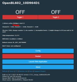
    - If I load the BL0942 driver manually, everything works perfectly; if I load it from the startup command, the unit becomes unreachable. I don't know why this happens. I think a work-around is to load the driver after a delay, but I saw a recent post saying delay and delay-ms don't (yet) work in the backlog command.
    - On the wifi module, GPIO22 from the BL602 appears to connect only to a 200K resistor that goes to 3.3V. I can't figure out what this is supposed to do or why it has been included in the circuitry.

    It's the national holiday in Canada at the beginning of next week, so I'll complete this thread and answer any questions in the middle of next week.

    Thanks again for all the help.
  • #15 21592243
    p.kaczmarek2
    Moderator Smart Home
    I don't have BL602 at hand at the moment, but it seems that BL602 has LFS and scripting enabled, so after recent changes backlog with delay should work as well.
    Is BL602 startup command multiline?
    If so, you don't even need backlog, you could do:
    
    delay_s 5
    startDriver BL0942
    

    Of course, this doesn't change the fact that BL0942 shouldn't crash on startup.... @insmod any ideas?
    @DeDaMrAz do you have BL602 to check?
    Helpful post? Buy me a coffee.
  • Helpful post
    #16 21592257
    insmod
    Level 25  
    >>21592243
    Well, the first idea is that uart can't be enabled early after boot.
    To test, enter into startup command "uartInit 9600". If the problem is in uart, then BL602 should hang.
  • #17 21592374
    p.kaczmarek2
    Moderator Smart Home
    Well, I seem to remember that I am the one who added UART on BL602... and a brief search of forum seems to confirm that. Futhermore, there was no such reports before, so it may indicate that either something else is wrong or the new SDK is at fault. The one with WiFi encryption update.
    Helpful post? Buy me a coffee.
  • ADVERTISEMENT
  • Helpful post
    #19 21593308
    divadiow
    Level 35  
    same. Nothing in log though, just loops.

    here are a couple of reboots

    Code: Text
    Log in, to see the code
  • Helpful post
    #20 21593350
    p.kaczmarek2
    Moderator Smart Home
    Does pre-SDK change BL602 bootloop as well?
    Helpful post? Buy me a coffee.
  • #22 21593378
    divadiow
    Level 35  
    1.18.95 https://github.com/openshwprojects/OpenBK7231...mmit/5916fbd8a7703368aa07891822261f6b75c5f0f2

    Added after 9 [hours] 41 [minutes]:

    Code: Text
    Log in, to see the code


    in startup command or autoexec for me on 1.18.90 does not cause boot loop.

    extend the delay to 10s on 1.18.127 and it seems to be OK.

    enable flag 26 ([UART] Use alternate UART for BL0942, CSE, TuyaMCU, etc) on 1.18.127 and the log out no longer goes silent after starting bl0942 and does not boot loop with delay_s 5
  • #23 21597138
    divadiow
    Level 35  
    >>21584971

    Thanks for the fw backup. Here's boot log for the record.

    Code: Text
    Log in, to see the code


    do you have a working template/config for this device now @ProfAnderson ?
  • Helpful post
    #24 21598436
    ProfAnderson
    Level 4  
    I've posted a full teardown with images and documentation on the pinout for the PTBLU-W wifi module.
    https://www.elektroda.com/rtvforum/topic4129041.html#21598413

    I'll give any further updates on technical details of the module or overall circuit breaker in that posting.

    @divadiow - I have a working config now, but still experiencing some problems. e.g. I haven't figured out how to use the BridgeFWD/REV roles for controlling the relay. In one of his last postings https://github.com/openshwprojects/OpenBK7231T_App/issues/667#issuecomment-1429877635 , valekCN referred to creating documentation ("I have not yet updated README will do it soon"); either it's not yet done and/or I'm not sure where to look. Other issues are almost certainly related to me being very new to OpenBK and just learning how things work. Thanks.

    P.S. Please let me know if my teardown isn't in the right section of elektroda.com and I'll move it!
    P.P.S I have a dual-pole version of this circuit breaker arriving in a few days. Hopefully it uses a known wifi module and not an entirely new and different one!!
    https://www.aliexpress.com/item/1005006390316904.html
  • #25 21598472
    divadiow
    Level 35  
    cool.

    I don't know much about the BridgeREV and BridgeFWD roles. I don't think I have ever had a device that needs them.

    Assuming it needs the bridge driver, it doesn't look to be enabled on BL602 though
    https://github.com/openshwprojects/OpenBK7231T_App/blob/main/src/obk_config.h#L178

    here's a build with it enabled: https://github.com/openshwprojects/OpenBK7231T_App/actions/runs/16091030578

    Screenshot of obk_config.h configuration file with line 178 regarding bridge driver settings highlighted.
  • #26 21599340
    ProfAnderson
    Level 4  
    Completed a teardown of the unit; this allowed me to trace the wiring and determine pinout. I got help along the way from forum members - Thank You!

Topic summary

The discussion focuses on identifying and obtaining the pinout for the WiFi module labeled PTBLU-W in the EARU EAKCB-EWE-M smart circuit breaker purchased from AliExpress, aiming to enable firmware flashing with alternatives like OpenBK or Tasmota. Initial attempts to identify the module suggested it might be an ESP32 or a CBU module, but after partial removal of the metal RF shield, the chip was identified as a BL602. The user sought pinout information referencing the Tuya CBU module datasheet and traced PCB circuits to verify power pins. Challenges included determining the BOOT pin necessary for flashing, as the BL602 differs from the BK7231N used in the CBU module. Suggestions included desoldering the metal shield or probing UART pins to identify TX for debug output. Flashing attempts with Boufallo Lab Dev Cube software faced inconsistent communication, resolved by switching USB-UART converters. Successful peeling of the metal shield enabled a near-complete pinout and firmware backup. Further discussion covered BL602 firmware behavior, including boot loops triggered by BL0942 driver startup commands in OpenBK firmware versions, with solutions involving delay adjustments and UART configuration flags. The main circuit board is identified as YK-DPN-T-V1-1 dated 2023-6-6. The module supports eWeLink and is compatible with BL602-based firmware modifications.
Summary generated by the language model.
ADVERTISEMENT