logo elektroda
logo elektroda
X
logo elektroda

BK7231T WB2S - Lumary RGBWW LED Einbaustrahler 12W

guthpascal 852 5
ADVERTISEMENT
  • #1 20311467
    guthpascal
    Level 2  
    Hello

    somehow I was able to flash the LED spot. On a second try I would also provide some pictures for the connections and write down the whole process.

    It's really a good nice light to buy. Sometimes they are cheap for only 20€ for a set of two. Pretty amazing.

    For now I just couldn't find any instruction how to find out the config I have to do in openbeken. I only found a sentence it is easy to find out if I don't know. How? :-) Can someone please explain me how to find out the pins that I do have to set in the config?

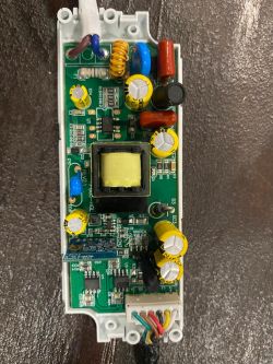
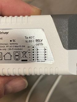
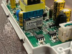
    Attached a few pictures already of the opening that could help.

    BK7231T WB2S - Lumary RGBWW LED Einbaustrahler 12W
    BK7231T WB2S - Lumary RGBWW LED Einbaustrahler 12W


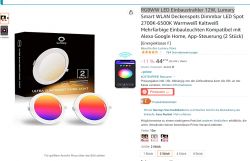
    BK7231T WB2S - Lumary RGBWW LED Einbaustrahler 12W
    BK7231T WB2S - Lumary RGBWW LED Einbaustrahler 12W
  • ADVERTISEMENT
  • Helpful post
    #2 20312299
    p.kaczmarek2
    Moderator Smart Home
    Hello, do you have OpenBeken already flashed?

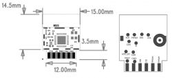
    This device is using WB2S and has RGBCW outputs. So it requires 5 PWMs. One for each color.
    BK7231T WB2S - Lumary RGBWW LED Einbaustrahler 12W
    Here is the pins table:
    in No.SymbolI/O typeFunction
    1VBATPPower supply pin (3.3 V), which is connected to the VBAT pin on the internal IC
    2PWM2I/OCommon GPIO, which is connected to the P8 pin on the internal IC
    3GNDPPower supply reference ground pin
    4PWM1I/OCommon GPIO, which is connected to the P7 pin on the internal IC
    51RXI/OUART1_RXD, which is used as a user-side serial interface pin and is connected to the P10 pin on the internal IC
    6PWM0I/OCommon GPIO, which is connected to the P6 pin on the internal IC
    71TXI/OUART1_TXD, which is used as a user-side serial interface pin and is connected to the P11 pin on the internal IC
    8ADAIADC pin, which is connected to the P23 pin on the internal IC
    9PWM4I/OCommon GPIO, which is connected to the P24 pin on the internal IC
    10CENILow-level reset, high-level active (internally pulled high) Docking IC-CEN
    11PWM5I/OCommon GPIO, which is connected to the P26 pin on the internal IC

    As you can see, PWMs are available on pins P26, P24, P7, P6 and P8.

    If this device is using raw PWMs for LED control, then config should be easy. There is a slight chance there is a dedicated LED driver on board (please give all IC names?), but let's assume it's raw PWM.

    You should go to Options->Configure Module and set PWM roles for these pins, and assign them channels. Channels 1, 2, 3 and 4, 5.
    BK7231T WB2S - Lumary RGBWW LED Einbaustrahler 12W
    Then you should play around with LED controller to see which colors are swapped.

    PWM with channel 1 is red, with channel 2 is green, with channel 3 is blue, etc. RGBCW.

    But you don't know if PWM on P26 is used for red or for green - it can be used for any colors. That's where you have to test and guess.

    So you adjust the PWM ->channel mapping to match the correct colors.

    Second options: just look on the traces of PCB, check them with multimeter and see where each trace goes..

    Does this device also have a button or a WiFi LED?
    Helpful post? Buy me a coffee.
  • ADVERTISEMENT
  • #3 20312901
    guthpascal
    Level 2  
    Wow thanks a lot. This was a really good helpful answer.

    After having this knowledge from you I was able to set it up correctly. I was just giving it a try for the basic raw. Turned out only a few colors were twisted.

    Anyway to get back to your questions. No buttons or Wifi LEDs on the board. There are two MC1051 ICs on board.

    Here is the correct config for the light:

    P6 - PWM 3
    P7 - PWM 2
    P8 - PWM 1
    P24 - PWM 5
    P26 - PWM 4

    I will try again to flash another one again because I did it few weeks ago and post a picture for the connection points I used.

    Once again thanks a lot. Hope with the mqtt it will also solve my connection problems once in a while.
  • ADVERTISEMENT
  • Helpful post
    #4 20312941
    p.kaczmarek2
    Moderator Smart Home
    Good job, you figured out it really quick.

    Futher flashing photos with solder points would be very useful for our users, so please post them if you can.

    Tell me if you need any further guidance with MQTT or anything. I can also help you with flashing other devices, if you have any. Including non-Beken one. We have support for BL602, XR3, W600, W800 and more.... and more coming soon.
    Helpful post? Buy me a coffee.
  • ADVERTISEMENT
  • #5 20313656
    guthpascal
    Level 2  
    Sure I will post it in the next days. Have 32 of these lights at my house so I will do a lot of flashing. :-)
  • #6 20313674
    p.kaczmarek2
    Moderator Smart Home
    Remember that with OpenBeken, if you just want, you can do much more "hacking" and DIY very easily. You can add extra buttons to those controller, for example "Button_NextColor" to iterate fixed list of colors, or Button_Dimmer, to adjust LED strip brightness by holding a button, or just button to toggle it on and off.... You can also group devices together by using Tasmota Device Groups (OBK has compatibility with them).
    Helpful post? Buy me a coffee.
ADVERTISEMENT