logo elektroda
logo elektroda
X
logo elektroda

LUATOS ESP32C3 Board - Issues Flashing D4 LED with Arduino 2.0

Michal_212 2259 17
ADVERTISEMENT
Treść została przetłumaczona polish » english Zobacz oryginalną wersję tematu
  • #1 20358412
    Michal_212
    Level 3  
    Hi

    I have a module bought on Allegro which has an ESP32-C3 chip, 4MB (32Mb) flash memory, USB C socket with USB - UART converter, two LEDs and two RST and BOOT buttons built in. Here is the Chinese website for this module with information about it: https://wiki.luatos.com/chips/esp32c3/board.html

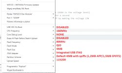
    I have Arduino 2.0 installed, in the board manager I installed the ESP32 package. I selected "ESP32C3 Dev Module" from the list of available boards. I wanted to upload a simple program that flashes the D4 diode (GPIO12). I have the settings in Arduino as follows:
    LUATOS ESP32C3 Board - Issues Flashing D4 LED with Arduino 2.0

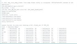
    I compile and upload the code, I have no errors. It's just that I don't flash the D4 diode, and in the terminal I get something like this:
    LUATOS ESP32C3 Board - Issues Flashing D4 LED with Arduino 2.0

    As if something else was uploaded? What is it about? Apparently my program uploaded via UART.
    Do you have a problem with Arduino? Ask question. Visit our forum Arduino.
  • ADVERTISEMENT
  • #2 20358530
    inot
    Level 37  
    Arduino settings correct.
    The only thing to question is the JTAG Adapter.
    Show what program you uploaded (or where you downloaded it from).
  • #3 20358577
    Michal_212
    Level 3  
    The programme is not fancy. The whole thing looks like this:

    Code: Arduino
    Log in, to see the code


    Not even UART support here so nothing I should rather receive in the terminal.
  • #5 20358671
    khoam
    Level 42  
    Michal_212 wrote:
    As if something else is uploaded? What is it about? Apparently my program loaded via UART.
    Probably there is a Lua interpreter "preloaded" in this board and specific flash partitions are created. I suggest to start by activating the option " Erase All Flash Before Sketch Upload " (at the moment you have Disabled) and load the test program again.

    inot wrote:
    The only thing that can be challenged is the JTAG Adapter.

    For this board model, this cannot be challenged.
  • ADVERTISEMENT
  • #6 20358685
    urkotrebor
    Level 21  
    What is displayed in the terminal is a kind of ESP32 business card , this is how I have at least on the boards I have , this happens after every reset .
    The LED does not flash because if I remember correctly it is connected to GPIO2 (pin 2).
  • #7 20358689
    khoam
    Level 42  
    urkotrebor wrote:
    What is displayed in the terminal is a kind of ESP32 business card, so I have at least on the boards I own, this happens after every reset .
    What is displayed in this case is the so-called "core dump" as a result of an error, so it certainly does not normally happen after every reset on other boards.

    urkotrebor wrote:
    The diode is not flashing because if I remember correctly it is connected to GPIO2 (pin 2).
    No, in the case of this board there are two diodes, on GPIO12 and GPIO13.
  • #8 20358697
    inot
    Level 37  
    urkotrebor wrote:
    The diode does not flash because if I remember correctly it is connected to GPIO2 (pin 2).
    It is not clear if the author has this one in mind. In addition, the processor detects the error: "flash config is corrupted".
  • #9 20358819
    Brendy8606
    Level 3  
    I programmed exactly this ESP.
    It also did not want to talk to me, but it is already working. Before connecting to the port, do you press boot to enter flash mode? Then release and load. Disconnect from power and reconnect to exit flash mode. And most importantly, what version of board?
  • ADVERTISEMENT
  • #10 20358881
    Michal_212
    Level 3  
    inot wrote:
    What this ESP looks like. There are different processor models.


    This is the ESP32-C3 chip.

    khoam wrote:
    I suggest to start by activating the option "Erase All Flash Before Sketch Upload" (at the moment you have Disabled) and load the test program again.


    Selecting this option does not change anything.

    inot wrote:
    It is not clear if the author has this one in mind. In addition to this, the processor detects the error: "flash config is corrupted".


    Yes, the program should flash the LED on GPIO12 pin i.e. D4.

    Brendy8606 wrote:
    Before connecting to the port do you press boot to enter flash mode? Then you let go and upload. Then unplug it and plug it back in to get out of flash mode. And most importantly what version of boardow?


    I am programming in this way. Up until about 2 weeks ago I was programming the ESP8266 similarly, without any problems.
    In the Arduino at the bottom of the window appears the charging progress which reaches 100% and after reset, the LED does not flash and in the console I have the above. If you mean the version in Arduino then I have installed ESP32 from Espressif version 2.0.6.

    khoam wrote:
    Probably there is a Lua interpreter "preloaded" in this board and specific flash partitions are created.


    Maybe this is where the problem lies? Maybe some other bootloader needs to be uploaded?
  • #11 20359090
    Brendy8606
    Level 3  
    I mean Board Manager,also take into account that Arduino above 2 still contains a lot of bugs.
    Try it on Arduino 1.8.16 and board version 2.0.5
    I've programmed 10 pcs recently and they all work and I didn't change any botloaders or other miracles bought from two different places.
  • #12 20359199
    khoam
    Level 42  
    Michal_212 wrote:
    Selecting this option doesn't change anything.
    Could you please post the Arduino IDE logs of flash cleaning and program loading?
  • #13 20361623
    Michal_212
    Level 3  
    I managed to upload the program correctly. I found on some Chinese forum that for a similar board in Arduino settings Flash Mode -> DIO must be selected. I had QIO changed to DIO and after uploading the program the LED flashes :)

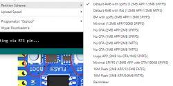
    By the way. Someone is able to explain to me what this setting is all about? With this Partition Scheme
    LUATOS ESP32C3 Board - Issues Flashing D4 LED with Arduino 2.0

    What is being set here?
  • #14 20361632
    khoam
    Level 42  
    Michal_212 wrote:
    What is set here?
    This is the partition scheme in flash. In brief: how much space for the program, how much for SPIFFS or OTA. For different flash sizes.
    Link .
  • ADVERTISEMENT
  • #15 20363245
    Michal_212
    Level 3  
    Ok, only from what I understand, it comes out that I can't use the whole 4MB for program code? At least I don't see a setting that would allow this, they all have APP and SPIFFS shared.
  • #16 20363289
    lopr_pol
    Level 32  
    The entire 4MB will not be given to you because there is still software such as wifi, tcp, etc. sitting around.
  • #17 20363313
    Michal_212
    Level 3  
    Well ok, but if I were to swap the Flash memory for a larger one e.g. 16MB (128Mb) then as far as I can see I only have a choice of two settings for that memory and the largest one only gives me 3MB for APP memory (i.e. I understand my code?) and 9.9MB for FATFS. And seriously more can't be allocated for program memory?
  • Helpful post
    #18 20363432
    khoam
    Level 42  
    Michal_212 wrote:
    if I would replace the Flash memory with a bigger one e.g. 16MB (128Mb) then as far as I can see I have only two settings for this memory and the biggest one gives me only 3MB for APP memory (i.e. I understand my code?) and 9.9MB for FATFS. And seriously more can't be allocated for program memory?
    From what I gather the largest partition size for a program is 4MB. I have never needed one that large. Of course then you need to generate your own partition scheme. In the case of the Arduino IDE you have to do some work to create such a custom scheme: Link .

Topic summary

The discussion revolves around issues faced while flashing a D4 LED (GPIO12) on a LUATOS ESP32-C3 board using Arduino 2.0. The user successfully installed the ESP32 package and selected the correct board but encountered problems with the LED not flashing after uploading a simple program. Responses suggest checking the JTAG adapter, ensuring the correct flash settings, and possibly the presence of a preloaded Lua interpreter affecting the board's operation. A key solution involved changing the Flash Mode setting from QIO to DIO, which resolved the issue. The conversation also touched on partition schemes for flash memory, indicating limitations on program memory allocation due to reserved space for other software components.
Summary generated by the language model.
ADVERTISEMENT