Please don't play around with phone while driving, IoT "hacking" can wait!
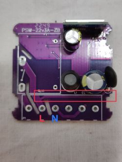
So the relay switch is here (unless I'm much mistaken), it connects L-in to L-out:
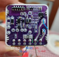
Ok, so if you markings are correct, then I'd say that L-in has to go somewhere to the power supply circuit. We know that L-in is here:
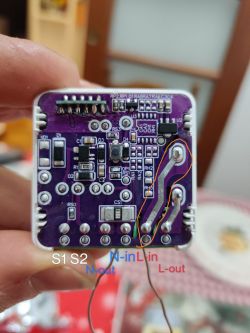
The question is - where does the L-in branches to the power supply to make 5V for Relay and later 3.3V for WiFi module?
Well, there are are two options:
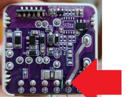
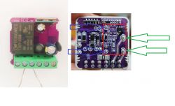
if it branches where the red arrow shows, at this joint, on the top of the PCB (top layer), then you can easily cut the trace to disconnect relay from L.
The option two is:
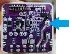
if it branches where I drawn the blue arrow (at the Relay pin, branches at the top layer of the PCB), then hacking this relay is hard, because cutting the trace won't just do the job...
At the moment I am not able to tell more. There are multiple ways to proceed from here. You can:
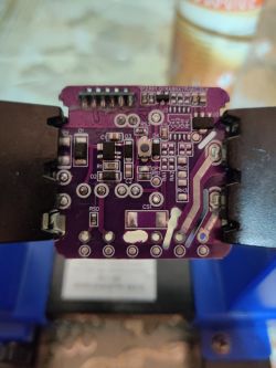
- just try looking at PCB?
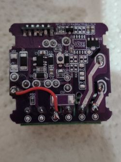
- just give it a try, cut of the trace going from L-in to Relay switch and check if board still powers on (if not, then that's not good, restore the trace, board is not easy to modify)
- just desolder relay with flux and solder wick...


