logo elektroda
logo elektroda
X
logo elektroda

Modifying Zigbee TS0004 4-Gang Switch for Dry Contact Outputs

Giupez 705 4
ADVERTISEMENT
  • #1 21464949
    Giupez
    Level 2  
    Hello everyone,

    I have a Zigbee TS0004 4-gang switch module, and I would like to modify it to obtain dry contact (voltage-free) outputs on all four channels. Currently, the module outputs a switched live (phase), but I need it to function as a simple relay without passing mains voltage.

    What I Need:

    A way to modify the TS0004 hardware to disconnect the internal connection to mains voltage and make the relays act as pure switches.

    A wiring diagram or photos of any successful modifications.

    Confirmation if this modification is even possible without damaging the device.


    My Use Case:

    I need to control a 5V circuit, so I cannot use the standard phase-switched output. If hardware modification is too complex, I am open to using external relays, but I’d prefer a direct modification if feasible.

    Has anyone successfully modified the TS0004 (or a similar Tuya relay module) to achieve dry contacts? Any guidance, diagrams, or alternative solutions would be greatly appreciated!

    Thank you in advance for your help!

    Best regards,
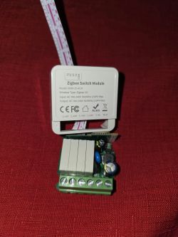

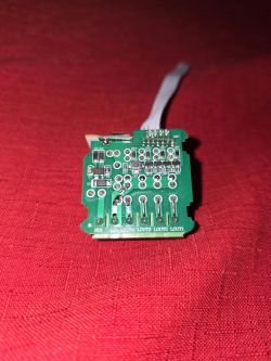
    Zigbee switch module shown on a red background.
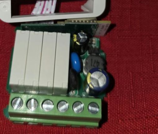
    Circuit board on a red background.
  • ADVERTISEMENT
  • #2 21464984
    p.kaczmarek2
    Moderator Smart Home
    It's certainly possible, we already had similar topic: Modifying Tuya Mini Smart Switch for Dry Contact Use - Guidance Needed.

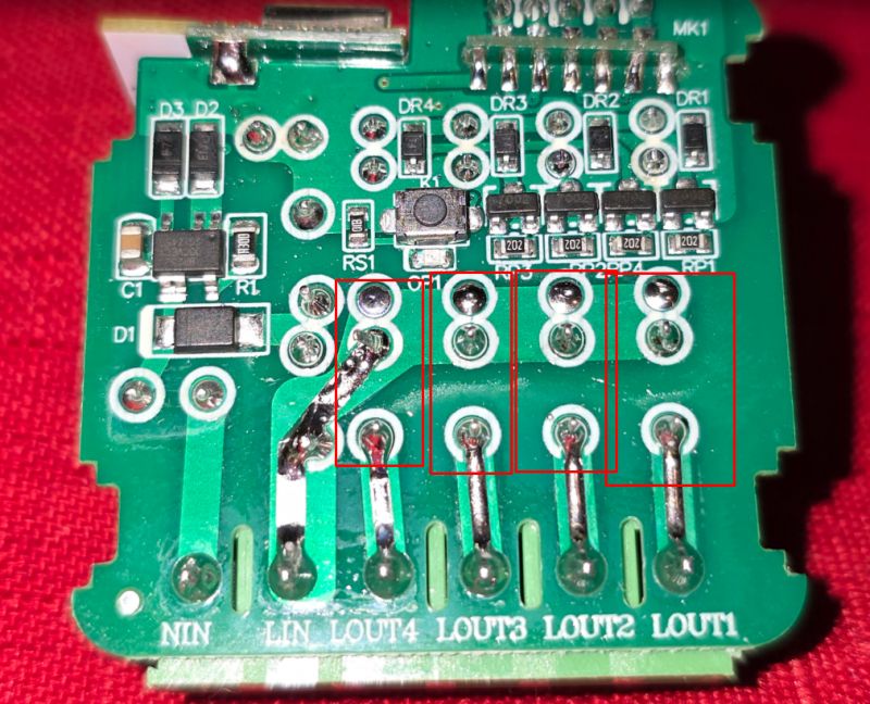
    On your board, I can see clearly 4 transistors used to drive relay coils and I can also see clearly the pins of relay switches:
    Electronic circuit board with various components, such as resistors and diodes.
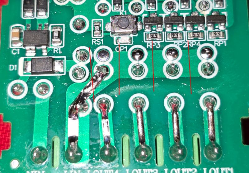
    I can't clearly see how L (Live wire) goes futher into the board, but it seems there is one pin before trace turns towards relays, and if that's the case, you need to do following cuts:
    Close-up of a circuit board with electronic components and soldering points.
    This is, of course, under assumption that your board is one-sided and that the trace is not on the other side of the board. Futhermore, you need to pay extra attention to keep clearance large enough for mains voltage. You can't just do one mm cut, this could be a serious safety risk. Check the distance between Lin and Lout4 traces and maintain at least such clearance.

    Another question would be how are you going to route out the extra relay wires? But maybe if you drill holes in case... still, that's not as nice as screw terminal block...

    So, summing up, the modification in this case is possible and I would even say it's fairly simple, but it's still not recommended and can pose a shock threat if done incorrectly. Think twice and if you decide to do it, please be careful and keep track clearances so there is no risk of getting L potential where it shouldn't be.

    Also, after you do the cutting, check with multimeter (continuity check) to be sure.

    Let me know if i can help any futher, and if you decide to do the mod, maybe show us photo after it's done.
    Helpful post? Buy me a coffee.
  • ADVERTISEMENT
  • #3 21465139
    Giupez
    Level 2  
    I appreciate the insights on modifying the TS0004 to achieve dry contact outputs. Now, I have a couple of questions.

    Would it be possible to modify the TS0004 to operate on a 5V power supply instead of 230V AC?

    The relays inside likely require a higher voltage for coil activation. Could they be replaced with 5V relays?

    The internal power supply circuit is designed for 230V. Would bypassing or replacing it with a 5V DC regulator be feasible?

    If modification isn’t possible, would using an external 5V-controlled relay board be the best alternative?

    Furthermore, what do you mean by "how are you going to route out the extra relay wires?"

    Thanks in advance!
  • ADVERTISEMENT
  • #4 21465237
    p.kaczmarek2
    Moderator Smart Home
    Well, first you need to check the relay model. Can you give relay photo from side? Is there any marking?

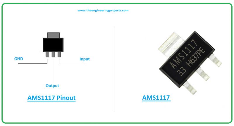
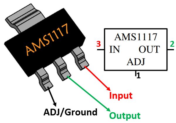
    Your device seems to be using a standard non-isolated step down converter like BP2525 to convert 230V (well, rectified...) to 12V or 5V. I can also see AMS1117-3.3V on the board, so it may be fair to say that it is actually using 5V to drive relays. They wouldn't be using such a simple LDO like AMS1117-3.3V with 12V on input, in the case of 12V they would use a secondary step down converter. AMS1117-3.3V is used on lower voltages to reduce heating losses.

    Futhermore, I actually saw similar relays in the past. I've presented them in some of my teardowns. Have you seen this topic?
    https://www.elektroda.com/rtvforum/topic4045441.html
    Well, in that topic, I've shown the similar relay model to be actually 5V-powered. It was HF49FD 005-1H11T, 5A 250VAC.

    So I would say it's fairly likely that your device is actually using 5V internally, but we still need to verify it. What is the marking on the relay? Or maybe you can take a measurement?

    U2 is most likely the mentioned AMS1117-3.3V:
    Circuit board with electronic components on a red background.
    Pinout diagram and photo of AMS1117 voltage regulator.
    AMS1117 integrated circuit with labeled pins and functions.
    I'd suggest the following experiment:
    1. disconnect device from mains, disconnect all wires
    2. solder carefully two wires, one to U2 (AMS1117) input (5V) and second to U2 (AMS1117) ground (GND). Alternatively, you can use multimeter to find where U2 Input/ground are connected for easier access
    3. Apply 5V to the wires, check if the device is still working.

    By routing extra wires I meant that converting to dry contacts will require you to add 4 more wires, one for each relay, and there isn't enough space on the PCB for extra screw terminals.
    Helpful post? Buy me a coffee.
  • #5 21467049
    Giupez
    Level 2  
    Hi!
    Thank you for your reply.
    It turns out that I mistakenly bought the Zigbee version not the WiFi.
    So mine requires a specific hub, I have exchanged the product and I am waiting for the right one.
    I was able to inject 5v to the AMS1117, that I saw but did not think to directly operate from input pins. It turned up but again not able to see if it was working without Zigbee module.

    I will need it to operate at 5v, maybe I could use it without dry contact mod. I will post again once it arrives.
    Thank you for know
ADVERTISEMENT