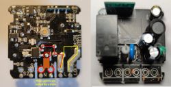
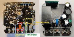
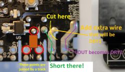
I know that in the past I have shown how to do it precisely in Paint on the picture submitted by user, but in case of your picture, I can't see exactly how are the traces routed. It seems that contrast is insufficient or the black soldermask makes it less readable.
The general rule of thumb is that you need to:
1. find out where the relay contacts are (normally closed, normally open, and common):
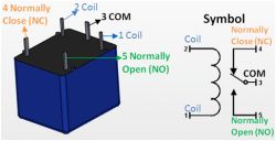
2. find out how 230V (or 120V, depending on your country) goes to the power supply circuit (full bridge rectifier, etc)
3. find a way to cut out totally the mains power from the relay contacts but still route them out so they can be used as a dry relay. Depending on the board design, it may be problematic and require making an extra route with an isolated wire
Maybe posting a top side of the board could help with locating the relay, but still you'd need to track the traces correctly.
Maybe is relay there?
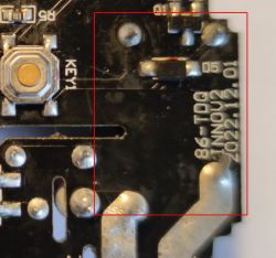
If that's where relay is, then you might need to cut L in such a way that it is still connected to the power supply, but does not connect to relay, but you would still need to somehow route out the second wire from relay...


