logo elektroda
logo elektroda
X
logo elektroda

Opening the chicken coop with the help of ESP32 - how to implement the mechanism?

xabro1 1629 26
ADVERTISEMENT
Treść została przetłumaczona polish » english Zobacz oryginalną wersję tematu
  • #1 20443532
    xabro1
    Level 5  
    Hi, I'm planning to cheaply realise an automatic opening of the chicken coop and I don't know what to use for pulling/winding the cable connected to the door.
    I was initially thinking of a weight or a tension spring, which would pull the door in the direction of opening and the door would be held in the closed position by the electric door opener. ESP + relay would trigger the electric door opener so that the door would open.
    I am thinking, however, whether it would not be better, and certainly cheaper, to use a car wiper motor or windscreen wiper motor. These can be bought for £10, the question is whether they can be controlled in a 'simple' way. I found out that the wiper motor has a crank mechanism, so that with a long enough arm it would manage to open the door, and returning the arm to the start position should not be a problem if the door opens sideways or, in the case of the flap and guillotine, has some sort of latching mechanism.
    The shaft motor would give the possibility to close the poultry house, but what about possible obstacles and motor overload?

    What about the control, I would like to stay with the ESP, because I still intend to use reed switches to verify if the poultry house is closed (sometimes it happens to forget if it is closed or not) and control the lighting.
  • ADVERTISEMENT
  • #2 20443556
    Walery K
    Level 23  
    I used such a motor to drive a sliding door into a room using a wire in a loop. On the axis of the motor there was a "pulley" and at the other end also a door wheel attached to the wire drove left and right depending on the direction of rotation of the motor. ESP has to drive two relays which will change the polarity of the voltage on the motor and preferably also have a lock on them so that accidentally both relays do not switch on at the same time. Of course, you will need limit switches in the end positions from which you will get information about the position of the door
  • #3 20443898
    xabro1
    Level 5  
    @walerik I don't quite understand. The crank mechanism in the wiper motor makes the wiper move left right with a constant voltage polarity.
  • ADVERTISEMENT
  • #4 20443947
    Walery K
    Level 23  
    Added after 1 [hour] 12 [minutes]:

    When you remove the locking mechanism inside the gearbox it all spins around.
    Although as I thought about it, this may be implemented differently today, because as I described it was in old Polish cars. But since the engine spins all the way around, it is enough to remove the eccentric from the engine axle and put a "pulley" in its place .
  • #5 20444155
    stefan_marek
    Level 18  
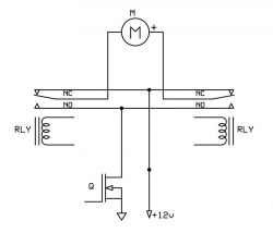
    There are many (front) wiper motors whose axis makes a rotary movement and the external mechanism only converts it into a left-right movement. Relays connected in a circuit, as in the attached fragment of the diagram, do not cause short circuits, even if both were driven at the same time. In addition, I have included an N-mosfet, which allows the motor to start and stop smoothly (as long as you have a free GPIO with PWM support in your ESP). In the program, you first turn on the relay, and after a short delay the PWM control when starting the motor, and when stopping you first reduce the PWM and then turn off the relay. This prevents sparking and contact burnout. I have a sliding gate about 3 m wide that is driven this way. I first used a wiper motor and now use a geared motor from a 12V screwdriver. Here I have the option of using an overload clutch as a safety device in emergency situations. I use pre-polarised small magnet reed switches as limit switches, which then work as bistable. Opening the chicken coop with the help of ESP32 - how to implement the mechanism? .
  • #6 20444234
    andrzej lukaszewicz
    Level 41  
    A simple cheap 12/24V power jack with built in limiters. I have done a dog box door lock on this and it has worked for 5 years.
  • #7 20444607
    xabro1
    Level 5  
    Walery K wrote:
    When you remove the locking mechanism inside the gearbox it all spins around.

    I had in my mind a mechanism like in this video https://www.youtube.com/watch?v=F2HwTJLywZM which I found here on the forum. In any case, any type of windscreen wiper would be more likely to be used to open the door.

    stefan_marek wrote:
    In the program, you first turn on the relay, and after a short delay the PWM control when the motor starts, and when it stops you first reduce the PWM and then turn off the relay. This prevents sparking and contact burnout. I have a sliding gate about 3 m wide that is driven this way. I first used a wiper motor and now use a gear motor from a 12V screwdriver. Here I have the possibility of using an overload clutch as a safety feature in emergency situations.


    This means that the mosfet will pass current at increasing intervals, causing the motor to stop gradually. Am I understanding this correctly

    I was also thinking about using a screwdriver with a clutch, as I would have overload protection straight away, which I was also considering. What bothered me was the torques, which I don't quite understand, and the speed control.

    andrzej lukaszewicz wrote:
    A simple cheap 12/24V power jack with built-in limiters.


    I was also thinking about this, but I would like to open two chicken coops, and the cost of such a power jack is more than 100 zł, which is almost 300 zł when buying 2 pieces.
    Browsing through the actuators on OLX, I found central locking or boot actuators. Do they perform a movement like the power jack? This would be a nice alternative to the electric deadbolt I was thinking of at first.

    Can the overload issue be solved somehow? Whether it's the motor from the drill, the wipers or the glass. It can always happen that something falls and blocks the door, what then? Is there any way of recognising such an overload condition electronically?
  • #8 20444908
    Walery K
    Level 23  
    Electronically, with a constant voltage supply there is no problem in determining whether something has blocked your door. You simply measure the motor current and if it is overloaded, the current increases.
    And just out of curiosity, how do you currently have the door open?
  • ADVERTISEMENT
  • #9 20446217
    xabro1
    Level 5  
    The door hangs on a hinge and opens sideways. They are locked with a latch, so they are naturally opened manually. Now I've only just thought of the fact that in a rope scenario it would also be useful to lock these doors. From the outside, no animal will open them, because they don't open inwards, but if they are pushed from the inside they will open. Perhaps it would be possible to use the central locking motor to move the latch and then activate the cable pull. Although in this case the cable pull would already be better implemented with a weight.
  • #10 20446444
    Walery K
    Level 23  
    If the opening is on a hinge placed on the side then unfortunately a linear actuator would be the best solution. How about moving the hinge to the top edge and then opening would be very simple by winding the cable onto a wheel placed on the motor axis and closing by unwinding the cable and the door would fall under its own weight?
    And would this slider then be necessary?
  • ADVERTISEMENT
  • #11 20446501
    ta_tar
    Level 41  
    For example, see this mechanism Pipe ball valve controller 1/2″ ZigBee 3.0 TUYA" with a little modification, it might be able to open the door.
  • #12 20446508
    andrzej lukaszewicz
    Level 41  
    xabro1 wrote:
    I was also thinking about this, but I would like to open two chicken coops, and the cost of such a power jack is more than 100 zł, which is already almost 300 zł when buying 2 pieces.
    If you think you will do it cheaper, you are wrong. I've given you a tried and tested solution, butchering the wiper gears will take more than £300 worth of time, and you will still need to buy various other components.
  • #13 20446523
    Ryszard49
    Level 38  
    I don't know what kind of windscreen wiper drive motors you have, but mine only turn one way.
  • #14 20446536
    zdenek_zdenek
    Level 27  
    Stepper motor, gearbox, screw, nut, all put together and you have a mechanism. i would add two more stops. No locks or latches needed.
  • #15 20446610
    Ryszard49
    Level 38  
    zdenek_zdenek ,wrote:
    Quote:
    Stepper motor, gearbox, screw, nut,all put together and you have the mechanism. i would add two more stops. You don't need any locks or latches
    But you got worked up and forgot that you still need a motor controller + pulse generator not to mention a lock/open cycle controller.
  • #16 20446675
    gregor124
    Level 26  
    If only opening then it will probably be easier to use a permanent magnet in the door and an electromagnet on the frame and some iron so that the permanent magnet can hold the door in the closed and open positions. The electromages could normally be unconnected and, with the right polarity, push back the door with the permanent magnet. In addition, a sufficiently strong permanent magnet could prevent the door from opening and/or closing on its own.
  • #17 20446722
    zdenek_zdenek
    Level 27  
    Ryszard49 wrote:
    pulse generator not to mention the controller for the closing and opening cycle.


    The ESP will be used for this


    I didn't write about the motor controller because it's obvious that it has to be there in the first place, secondly I only described the mechanics side as briefly as possible.

    There could also be a DC motor instead of a stepper, then the control would be simplified, but the project gets less ambitious.
  • #18 20446734
    Walery K
    Level 23  
    gregor124 wrote:
    If only opening then it would probably be easier to use a permanent magnet in the door and an electromag on the frame and some iron so that the permanent magnet could hold the door in the closed and open position. The electromages could normally be unconnected and with the right polarity push the door back with the permanent magnet. In addition, a sufficiently strong permanent magnet could prevent the door from opening and/or closing on its own.

    I would be concerned that if the door pi...ng when opening and closing, you would stress the hens so much that they would stop laying eggs.
  • #19 20446835
    Ryszard49
    Level 38  
    Just search under the keywords: automatic henhouse doors Smart doors and we have a multitude of solutions. And on You Tube you can learn about the advantages and disadvantages of the proposed solutions.
  • #20 20446936
    gregor124
    Level 26  
    Walery K wrote:
    gregor124 wrote:
    If only opening then it would probably be easier to use a permanent magnet in the door and an electromag on the frame and some iron so that the permanent magnet could hold the door in the closed and open position. The electromages could normally be unconnected and with the right polarity push the door back with the permanent magnet. In addition, a sufficiently strong permanent magnet could prevent the door from opening and/or closing on its own.

    I would be concerned that if the door when opening and closing pi.

    It is always possible to adjust the strength of the solenoid, you can also add a spring, you just need a little creativity.
  • #21 20447038
    Walery K
    Level 23  
    As I wrote, the linear actuator is the simplest, you can find one at Chinese brothers for less than £ 100.
  • #22 20447668
    kaczakat
    Level 34  
    I found a ready-made lifting door made of cheap plastic on Allegro for about a hundred bucks, terrible quality, maybe it would last a summer season. The aforementioned power jack actuator for a swing gate works OK, it has built-in limiters, you just need to give it power for a time not shorter than the required opening, the limiters are set to operate when you want, there is no full opening of the door but why should there be, DC motor controller for about £10 "STEPPING MOTOR CONTROLLER MODULE L298N ARDUINO", 2A is enough, 19V 3A power supply from an old laptop, although the actuator supposedly requires 24-36V, simply has less power and lower current consumption. Such an actuator, however, is 2 hundred pounds lightly. The stepper motor module can of course be used with a DC motor, the controller is an ESP8266. I need to add a button to open manually and a limit switch to confirm that it is open or closed. It would be nice if it was in WIFI range, then it gets the time from the NTP server, with a simple algorithm you can open and close at a calculated time for sunrise and sunset, or add integration with some domoticz or HA. You do not need to write any special programme, you can upload the tasmot and set the schedule permanently, the on-off option only switches the direction of opening, the actuator remains in the position after switching off the limit switch and does not consume electricity as, for example, an electromagnet, the tasmot also has WWW, through which you can change the state of the switch with your finger.
    Helpful post? Buy me a coffee.
  • #23 20453884
    oskar007PL
    Level 1  
    Hello
    I will give you my solution, which has worked for several years. It is simple and rather reliable. A window blind works as a door, controlled by a timer e.g. like for an energy meter. In the morning around 8 it is opened and around 18 it is closed. The control of the roller shutter is, of course, free. It can also be remote controlled. Regards
  • #24 20454768
    xabro1
    Level 5  
    Walery K wrote:
    Maybe move the hinge to the top edge and then opening would be very simple by winding the cable onto a wheel placed on the motor axle and closing by unwinding the cable and the door would drop under its own weight?

    This could pass the test.
    zdenek_zdenek wrote:
    Stepper motor, gearbox, screw, nut, all connect and you have the mechanism. I would add two more stops. No locks or latches needed.


    You mean a long threaded rod and a nut that rests on the rail that will slide? I've seen such a mechanism here on the forum and on YouTube. I guess it would be better to use a pulley and make some two grommets with some sort of end-activating element in between.

    gregor124 wrote:
    If only opening then it would probably be easier to use a permanent magnet in the door and an electromag on the frame and some iron so that the permanent magnet could hold the door in the closed and open position. The electromages could normally be unconnected and with the correct polarity push the door back with the permanent magnet.


    Electromagnet when activated would have the same polarity as the permanent magnet, causing the door to push back? What then of the piece of iron

    Walery K wrote:
    I would be concerned that if the door pi...ght when opening and closing, you would stress the chickens so much that they would stop laying eggs.


    Or they will lay immediately :D

    @kaczakat this module for the DC motor is it to be used for the linear actuator or for the motor option? I have some sort of 12 volt DC motor from an old children's vehicle, I just don't know how many A's it needs.
    I also found a 30W AC motor probably from a washing machine, probably from a water pump. Maybe it could also be used, just how to control the speed?

    @oskar007PL link does not work
  • #25 20454796
    Krzysztof Kamienski
    Level 43  
    gregor124 wrote:
    You can always adjust the strength of the solenoid, you can also add a spring, all it takes is a bit of creativity.
    No sense. Closing and opening that flap so violently can castrate a cock at any time. Check the gentlemen under , "model servos" :D .
  • #26 20454944
    kaczakat
    Level 34  
    @xabro1 this 2A module supports DC motors, it simultaneously supports 2 DC motors or 1 4-wire stepper motor. For an AC motor it is not suitable. You can apply voltage to left or right speed with it, I use it for a power jack actuator. An old car doesn't say much, it could be an RC model with 1W motors or a 50W/wheel drive 4x4, I used to have one that had 30A fuses, a 2A module would go up in smoke from looking at the car. I checked my actuator's draw is under 1A.
    Helpful post? Buy me a coffee.
  • #27 20454975
    zdenek_zdenek
    Level 27  
    An AC motor is not suitable because it will only rotate in one direction. Two relays and two limit switches are sufficient to drive a DC motor. To make a low-cost screw mechanism, you will need tools such as a drill, an angle grinder, a welding machine and a lathe, but you can easily do without it.

    A few centimetres of threaded rod is sufficient.

    Fix the screw on a lever attached to the door, and the screw drive on another lever to the wall also hesitantly, it can not be rigid.
    Look at how the mechanisms for opening gates are made, and you will know how to do it.
  • Topic summary

    The discussion revolves around implementing an automatic chicken coop door using an ESP32 microcontroller. Users explore various mechanisms for opening the door, including using a car wiper motor, linear actuators, and DC motors. Suggestions include employing relays for motor control, limit switches for position feedback, and considering the torque and speed control of the motors. Some participants recommend using a threaded rod and nut mechanism or a pulley system for simplicity. Concerns about the safety and stress on chickens during operation are also raised, alongside the potential for using electromagnets for locking mechanisms. Overall, the conversation highlights multiple approaches and components for creating a cost-effective automated door system.
    Summary generated by the language model.
    ADVERTISEMENT