logo elektroda
logo elektroda
X
logo elektroda

OpenBeken WS2812B driver (compatible with SM16703P, etc) - short scripting presentation

p.kaczmarek2 7791 52
ADVERTISEMENT
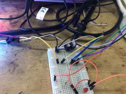
  • Test setup with LEDs in red, green, and blue on a workbench.
    Here I will show you the basics of individually addressable LEDs control in OpenBeken. Currently OpenBeken supports WS2812B LEDs and many LEDs with similiar protocols, like, for example SM16703P. In this topic I will focus on the basics of the manual LED control, I will not cover advanced animations here. The advanced animations system will be added, hopefully, soon, and it will be covered by a separate tutorial.
    For generic information about OBK, please see:
    https://github.com/openshwprojects/OpenBK7231T_App

    Which devices have individually addressable LEDs?
    There are many devices like that on the market, here are some examples:
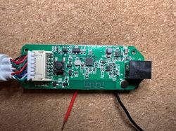
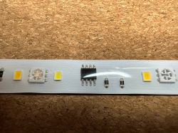
    - LSC Smart Digital LED Strip (2x5m RGBCW): BK7231N, SM16703P
    Packaging of LSC Smart Digital LED Strip
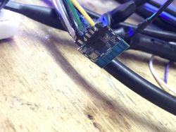
    Printed circuit board module connected to several colored wires on a cork background.
    Close-up of LED strip with integrated circuits and LEDs.
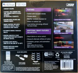
    - Feit Electric "Smart Color Chasing Strip Light" w/BK7231N and SM16703
    Feit Electric smart LED strip packaging. Feit Electric LED strip packaging with features.
    And much more.

    How to connect LEDs?
    LEDs can be only connected on P16, which is MOSI pin. This is because we're using SPI DMA driver to get precise timings.
    See our datasheet topic to locate P16:
    BK7231 datasheet, pinout, programming, specification, wiki (BK7231T, BK7231N)
    If your module has no P16 routed out, like a CB2S, you can always route it out yourself:
    How to access hardware SPI port on CB2S? P16 (MOSI) GPIO breakout method


    How to create a script in OpenBeken?
    Please refer to this tutorial:


    My testing environment
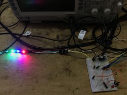
    I don't have any IoT device with individually adressable LEDs, so I just used a CB2S with routed out P16 pin (as in the guide which I mentioned earlier) with the WS2812B strip connected:
    LED strip with multicolored LEDs connected to a breadboard on a wooden table.
    Close-up of a breadboard with multicolored wires and electronic components connected. Close-up of an electronic module soldered to wires.


    Sample - RGB test
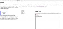
    Ok, so let's create a sample script. For now, we will just lit two LEDs, just to check if the strip is working. Here's how it looks like on my side:
    OpenBeken user interface with file editor and LED control scripts.
    Here's full script:
    
    startDriver SM16703P
    
    SM16703P_Init 3
    SM16703P_SetPixel 0 0 255 0
    SM16703P_SetPixel 1 0 0 255
    SM16703P_SetPixel 2 255 0 0
    SM16703P_Start
    

    The script is using SM16703P commands, but the same works for WS2812B. It's just that we have first developed SM16703P driver and then discovered that timings are also matching classic WS diodes.
    Result:
    Test setup with LEDs in red, green, and blue on a workbench.


    Sample - Full strip Single Color
    For this example, we can set all the pixels to a single color. There are two ways to do it. First one is to use a loop:
    
    startDriver SM16703P
    
    // number of LEDs
    setChannel 5 60
    
    // init
    SM16703P_Init $CH5
    
    // iteration variable
    setChannel 6 0
    
    // loop for each LEd
    again:
    SM16703P_SetPixel $CH6 0 255 0
    addChannel 6 1
    if $CH6<$CH5 then goto again
    
    // done
    SM16703P_Start
    

    Second way is much simpler - if you provide 'all' as pixel index, it will set all pixels:
    
    SM16703P_SetPixel all 0 255 0
    

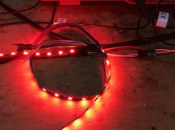
    Result:
    Individually addressable LED strip glowing red on a table.


    Sample - Full strip RGB
    A simple loop can be also used to set RGB colors. First red, then green, then blue, but the order of colors can be different if your strip is, for example, GBR standard.
    
    startDriver SM16703P
    
    // number of LEDs
    setChannel 5 60
    
    // init
    SM16703P_Init $CH5
    
    // iteration variable
    setChannel 6 0
    
    // loop for each LEd
    again:
    
    SM16703P_SetPixel $CH6 255 0 0
    SM16703P_SetPixel $CH6+1 0 255 0
    SM16703P_SetPixel $CH6+2 0 0 255
    addChannel 6 3
    if $CH6<$CH5 then goto again
    
    // done
    SM16703P_Start
    

    Result:
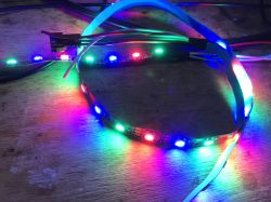
    LED strip with multiple colorful lights on a wooden surface.


    Sample - Basic Dimmer
    
    startDriver SM16703P
    
    setChannelType 1 Dimmer256
    
    // number of LEDs
    setChannel 5 60
    
    // init
    SM16703P_Init $CH5
    
    // on channel 1 dimmer change, refresh
    addEventHandler OnChannelChange 1 startScript autoexec.bat refresh
    
    // refresh function
    refresh:
    
    // iteration variable
    setChannel 6 0
    
    // loop for each LEd
    again:
    
    SM16703P_SetPixel $CH6 $CH1 0 0
    addChannel 6 1
    if $CH6<$CH5 then goto again
    
    // done
    SM16703P_Start


    OBK web panel (ignore the DDP for now):
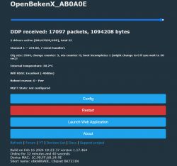
    OpenBekenX screen displaying packets and system settings
    Effects while playing around with dimmer:
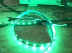
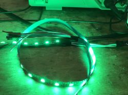
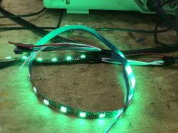
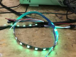
    LED strip with green-lit LEDs connected to a device. LED strip glowing green with connected wires. Green LED strip connected to a device on a wooden table. Illuminated LED strip on a wooden table with connected wires.

    Class LED controller (single color only)
    Another interesting possibility is 'hacking' the OBK script to control LEDs with old OBK single-color LED interface. For that, you need to enable the following flag:
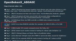
    Screenshot of OpenBekenX settings with Flag 4 option highlighted regarding RGBCW controller.
    Then, add the following script:
    startDriver SM16703P
    SM16703P_Init 60
    
    again:
    SM16703P_SetPixel all $led_enableAll*$led_red*$led_dimmer/255 $led_enableAll*$led_green*$led_dimmer/255 $led_enableAll*$led_blue*$led_dimmer/255
    SM16703P_Start
    
    delay_s 1
    goto again

    This will make OBK panel able to control the LEDs:
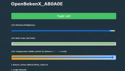
    Interface for managing LED lighting settings on the OpenBekenX platform.
    Everything except CW controls will work, even the dimmer and color picker:
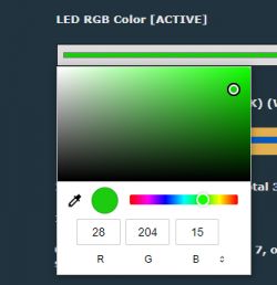
    RGB color palette with selected green color.

    Raw access
    It is also possible to send raw bytes stream via command. The bytes are sent directly, without converting to colors. This can be done via SM16703P_SetRaw command with the following syntax:
    
    SM16703P_SetRaw bUpdateAfterSet firstByte hexData
    

    Here is example usage:
    
    SM16703P_SetRaw 1 0 FF000000FF000000FF
    

    This will set first 3 LEDs to green, red and blue on WS2812B.


    Control via Home Assistant/HTTP
    Just like in Tasmota, all our commands can be executed via cmnd interface, so you can set colors directly from outside.


    Xlights control
    It is also possible to control LEDs via DDP protocol. Many applications like XLights can be used for that purpose:
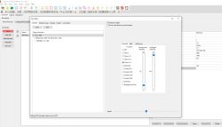
    Screenshot of the xLights interface with RGB light settings.
    Required setup on OBK side is minimal:
    
    startDriver SM16703P
    startDriver DDP
    SM16703P_Init 60
    

    Here are some sample effects made by DDP:


    Summary
    This is just the beginning of WS2812B LEDs adventure. For now, you can just script simple effects yourself or use DDP (with xLights, for example) for more advanced effects. The OBK-only animation system is not ready yet, but I am planning to add one soon.
    Stay tuned and let me know how I can improve the system!
    My current plan is to make also an automatic, user-friendly animations system with some animations that are built-in.
    The new system will work without any scripts, but I will publish more information once it's ready!

    Cool? Ranking DIY
    Helpful post? Buy me a coffee.
    About Author
    p.kaczmarek2
    Moderator Smart Home
    Offline 
    p.kaczmarek2 wrote 11885 posts with rating 9963, helped 569 times. Been with us since 2014 year.
  • ADVERTISEMENT
  • Helpful post
    #2 20966526
    jkwim
    Level 12  
    This is a great news indeed!

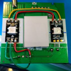
    I have requirement to be able to add a couple of WS2812B LEDs in to a Smart Wall Switch to be used as a Status Indicator Panel.

    Here is what I have done with a ESP8285 based switch and this works great. I am sending the LED commands via MQTT. Different color combinations for different statuses.

    Smart wall switch with LEDs in different colors. Printed circuit board with connected WS2812B LEDs and wires.
  • #3 20966545
    p.kaczmarek2
    Moderator Smart Home
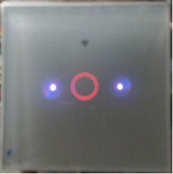
    It should be possible right now with the current scripting system.

    The only question would be does your light switches have P16 available?

    Otherwise you'll have to do the P16 hack I described here:
    How to access hardware SPI port on CB2S? P16 (MOSI) GPIO breakout method
    Helpful post? Buy me a coffee.
  • #5 20966577
    p.kaczmarek2
    Moderator Smart Home
    Hm okay, so please try doing that modification and we will try to add WS2812B LEDs to your wall switch.
    Helpful post? Buy me a coffee.
  • Helpful post
    #6 20966634
    jkwim
    Level 12  
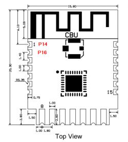
    The CBU based LQ-Y06 can be used as a LED Controller as well:

    Information sticker on AI Smart Remote Control Model LQ-Y06 with a QR code.

    Close-up of a circuit board with LEDs and technical markings.

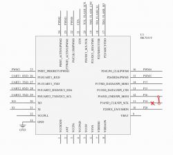
    Top view of the LQ-Y06 module with labels P14, P16 and the inscription CBU.

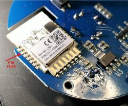
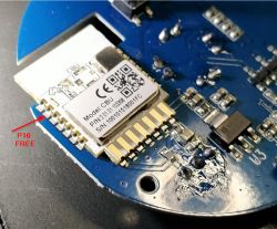
    CBU module on a round electronic board with P16 FREE marking.
  • ADVERTISEMENT
  • #7 20966716
    p.kaczmarek2
    Moderator Smart Home
    Sure, just route out the P16 and the ground. Then you can use external 5V power supply to power the LEDs. Connect all grounds together (don't forget, common ground is required), then P16 to the DIN of WS2812B strip and you can use this device as a LEDs controller.
    Helpful post? Buy me a coffee.
  • ADVERTISEMENT
  • #8 20967208
    bjoerns
    Level 2  
    Just tried it with the Battletron Lamp and it works. Colors are sometimes not really what you think (white is like a light purple) but it works stables, so thats a good start.
  • #9 20967239
    p.kaczmarek2
    Moderator Smart Home
    @bjoerns how that Battletron Lamp is organized, how many LEDs? I would like to help you with creating a final config for that. I am also still planning to add advanced animations system to OpenBeken. Hopefully, soon OBK will be able to control those LEDs without any prior scripting and setup.
    Helpful post? Buy me a coffee.
  • #10 20967277
    bjoerns
    Level 2  
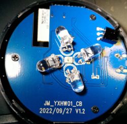
    The Battletron lamp uses two WS2811c Controller. One is controlling the nine LED's around the base, the second one powers the six LED's on the top.
    You can only control these two groups indiviual not the single LED's. So there is no chance of with very sophisticated effects etc. The only thing you could dow is something like a two tone effect.

    I just use the simple Autoexec.bat from above:
    startDriver SM16703P
    SM16703P_Init 2

    again:
    SM16703P_SetPixel all $led_enableAll*$led_red*$led_dimmer/255 $led_enableAll*$led_green*$led_dimmer/255 $led_enableAll*$led_blue*$led_dimmer/255
    SM16703P_Start

    delay_s 1
    goto again
  • #11 20967288
    jkwim
    Level 12  
    I tried to repeat my test from last year with WS2812B strip and came up with this slightly modified script:

    startDriver SM16703P
    
    // Channel for number of LEDs
    setChannel 5 16
    
    // init
    SM16703P_Init $CH5
    
    // Iteration Channel
    setChannel 10 1
    
    again:
    
    echo "1: $CH10"
    // Add 1 to Channel 10 with clamping between 0 to 15 and looping back to 0
    addChannel 10 1 0 15 1
    //                                         R B G
    //                                         R G B
    SM16703P_SetPixel $CH10 255 0 0
    
    SM16703P_Start
    delay_s 2
    SM16703P_SetPixel $CH10 0 0 0
    
    // loop for each LED
    goto again


    Basically I am looping a single dot across 16 x LEDs.

    I have been getting inconsistant results and have been scratching my head.

    LEDs 0,1,2 gets lit up correctly.
    Next LEDs 3 & 4 both get lit up at the same time
    Next LEDs 5 to 16 get lit up correctly

    Then I found that in the raw data log that 4 x bytes are being sent instead of 3 x bytes :

    Info:GEN:CHANNEL_Set channel 10 has changed to 6 (flags 0)
    
    Info:CMD:Set Pixel 6 to R 255 G 0 B 0
    Info:CMD:Raw Data 0xee 0xee 0xee 0xee - 0x88 0x88 0x88 0x88 - 0x88 0x88 0x88 0x88
                                            ^^^^ ^^^^ ^^^^ ^^^^
    Error:CMD:before enable tx 0x0000c20c
    Error:CMD:enable tx 0x0000c20d
    Info:MAIN:Time 43, idle 376416/s, free 75088, MQTT 0(2), bWifi 1, secondsWithNoPing -1, socks 2/38 
    Info:CMD:Set Pixel 6 to R 0 G 0 B 0
    Info:CMD:Raw Data 0x88 0x88 0x88 0x88 - 0x88 0x88 0x88 0x88 - 0x88 0x88 0x88 0x88
    Info:CMD:"1: $CH10"
    Info:GEN:CHANNEL_AddClamped channel 10 has changed to 7


    Can this be corrected?

    Added after 3 [minutes]:

    Another question is why the data has been manipulated ie. 0xEE instead of 0xFF and 0x88 instead of 0x00?
  • ADVERTISEMENT
  • #12 20967350
    p.kaczmarek2
    Moderator Smart Home
    @jkwim , I suspect that you are incorrect. The raw data is not the hex data you provided. Raw data is the data for the SPI, where we split each byte into 4 bytes for the SPI DMA transfer:
    Code: C / C++
    Log in, to see the code

    And the same, in the hex form:
    Code: C / C++
    Log in, to see the code

    Those are bit representations for, respectively, 0b00, 0b01, 0b10, 0b11. Each byte we send is split into 4 pairs of bits (4 * 2 = 8 bits) and then for each 2 bits (2^2=4 options) this array is looked up. This is why I think your reasoning is incorrect.

    Still, it doesn't explain you seem to be missing a LED! Which LED strip do you have? I will run your script on mine in a moment and check.

    Added after 1 [hours] 34 [minutes]:

    @jkwim , your script is incorrect. You start iteration with value 1 and futhermore increase the value first, so you skip LED 0 and LED 1. Here is corrected script:
    
    startDriver SM16703P
    
    // Channel for number of LEDs
    setChannel 5 16
    
    // init
    SM16703P_Init $CH5
    
    // Iteration Channel
    setChannel 10 0
    
    again:
    
    echo "1: $CH10"
    //                                         R B G
    //                                         R G B
    SM16703P_SetPixel $CH10 255 0 0
    
    SM16703P_Start
    delay_s 1
    SM16703P_SetPixel $CH10 0 0 0
    
    // Add 1 to Channel 10 with clamping between 0 to 15 and looping back to 0
    addChannel 10 1 0 15 1
    
    // loop for each LED
    goto again
    

    It seems to work well on my side:


    Helpful post? Buy me a coffee.

  • #13 20967558
    jkwim
    Level 12  
    Ok. Now I understand.

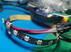
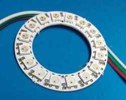
    I tried a normal WS2812B strip and also a WS2812B Ring.

    Same observation of LED 0,1,2 (2 lighting up very briefly) and then 3 & 4 getting lit at the same time and then 5 ...

    Close-up of a flexible WS2812B LED strip arranged in an arc on a blue work mat with attached wires.

    WS2812B LED ring with colored wires.
  • #14 20967607
    p.kaczmarek2
    Moderator Smart Home
    Can you make a video of my script running on your strip?

    Do you have PowerSave on?
    Helpful post? Buy me a coffee.
  • #15 20967634
    jkwim
    Level 12  
    Tried your script on both versions of LEDs. Same issue is there.

    Changed power supply also (I did the latest test plugging in to laptop USB port) just to eliminate one more variable.

    If there was transient data corruption issue it would not be the same two LEDs no.

    I am really confused. Perhaps something with the CBU module in this HW.

    Added after 19 [minutes]:

    I noticed that the following error message is firing continuously:

    Info:CMD:Set Pixel 0 to R 0 G 0 B 0
    Info:CMD:Raw Data 0x88 0x88 0x88 0x88 - 0x88 0x88 0x88 0x88 - 0x88 0x88 0x88 0x88
    Error:CMD:before enable tx 0x0000c20c
    Error:CMD:enable tx 0x0000c20d
  • #16 20968157
    p.kaczmarek2
    Moderator Smart Home
    This is just a debug text, I will remove it in the next build.
    I think we need more tests.

    Or maybe you're running something in the background, like IR interrupt?
    Helpful post? Buy me a coffee.
  • #17 20968181
    jkwim
    Level 12  
    I am really sorry for dragging this on.

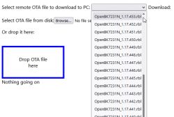
    The issue was with having the wrong version of FW.

    I was expecting to download the latest version and picked the topmost item which was actually 451 on that day (I have ignored the fact that the scroll bar was at the bottom not at the top).

    Screenshot of the software update interface with a drop-down menu of OTA file versions.

    When I looked at config page today suddenly I realized that the latest version is 469.

    Upgraded to 469 and all my issues were gone!

    Even the inconsistent color values are now good.

    My strip is a GRB strip so I need to specify the color values accordingly

    //  My strip is                      G R B
    //                                         R G B
    SM16703P_SetPixel $CH10 0 0 255


    Powersave is 0.

    Added after 39 [minutes]:

    After removing the delay statement from the loop this is the max speed that can be observed.


    My setup: Modifying CBU based LQ-Y06 IR Remote Controller to Support WS2812D LED Strip/Ring

    Sticker with information about AI Smart Remote Control on a black surface.
    CBU module on a blue PCB with P16 FREE label
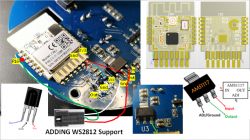
    Close-up of a circuit board modification for WS2812 LED support.
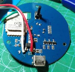
    A circuit board with electronic components, including a Wi-Fi module and wires.

    // WS2812B Test Script on CBU based LQ-Y06 IR Remote Controller
    
    startDriver SM16703P
    
    //setChannelType 1 Dimmer256
    
    // Channel for number of LEDs
    setChannel 5 16
    
    // init
    SM16703P_Init $CH5
    
    
    // on channel 1 dimmer change, refresh
    //addEventHandler OnChannelChange 1 startScript autoexec.bat refresh
    
    // refresh function
    //refresh:
    
    // Iteration Channel
    setChannel 10 0
    
    
    // loop for each LED
    again:
    
    echo "1: $CH10"
    //  My strip is                      G R B
    //                                         R G B
    SM16703P_SetPixel $CH10 0 255 0
    
    SM16703P_Start
    // introduce a delay to slow down the loop
    //delay_s 0.05
    //delay_ms 1
    
    SM16703P_SetPixel $CH10 0 0 0
    
    // Add 1 to Channel 10 with clamping between 0 to 15 and looping back to 0
    addChannel 10 1 0 15 1
    
    // loop for each LED
    goto again


    So I also can confirm that WS2812B support is good to go now.

    Will test the speed aspects using DDP next (above speed appears to be max based on the code execution speed in the loop).

    Added after 2 [hours] 13 [minutes]:

    DDP Test Successful
    Setup:
    I have a 180LED WLED (https://kno.wled.ge/) setup.

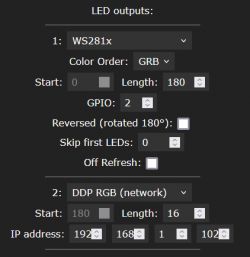
    Defined OpenBK device as 16 LED Length DDP string

    Screenshot showing LED output configuration settings for WS281x and DDP RGB.

    So now WLED will consider these extra 16LEDs as an extension to its physically connected LED string.

    Patterns will be displayed considering a total of 196 LEDs (180 + 16).

    Here are some sample videos. I have the WLED string wrapped on a tube. There is no physical connection from the last LED there. The pattern continues on the Ring which is the DDP string.

    (Note that there is a small issue with my setup in color mapping as a result of mixing RGB and GRB strings.)

    As you can see from the videos below, speed of LED response is not an issue.


  • #18 20968257
    p.kaczmarek2
    Moderator Smart Home
    So everything is working and you just had older version of firmware? That's a very good news! By the way, if you want to drive a really long LED strip, you can change the size of DDP buffer in the following way:
    
    startDriver DDP 1024
    

    where 1024 is the maximum size of allowed DDP packet in bytes.

    How long strip can you make? If you want, we can check how long strips are possible to control, but the limiting factor would be, I guess, UDP frame size?
    Helpful post? Buy me a coffee.
  • #19 20968297
    jkwim
    Level 12  
    1024/3=341 LEDs right.

    That would be plenty as in reality if DDP is used from another device like WLED, the cascading can be done on WLED on to another OBK device.

    Physically the LEDs can be scattered anyway right? For example a Christmas Garden Decoration.

    For my use I was more interested in modifying a Smart Wall Switch. I already have ESP8285 based one modified.

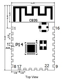
    Recently I bought few 4 x GANG one which were all CB3S ones. I want to give a try to modify one of them. Since P16 is not exposed in CB3S, it is definitely free for other use. The only thing needed is to open up the RF Shielding on the module and solder a wire I guess.

    Thanks for your effort in getting the drivers fixed.
  • #20 20968310
    p.kaczmarek2
    Moderator Smart Home
    The LEDs can certainly span among different devices so I guess we won't run into the buffer size problems anytime soon.

    Regarding the wall switch modification, do you have hot air? It will be needed to remove the shield.
    Helpful post? Buy me a coffee.
  • #21 20968314
    jkwim
    Level 12  
    BTW I would like to understand more about the RAW mode

    My requirement is to be able to update only one LED by specifying the LED number like
    SM16703P_SetPixel 5 00FF00


    SM16703P_SetRaw bUpdateAfterSet firstByte hexData
    
    SM16703P_SetRaw 1 0 FF000000FF000000FF


    What is the bUpdateAfterSet=1 value here?
  • #22 20968399
    p.kaczmarek2
    Moderator Smart Home
    Why do you want to use SM16703P_SetRaw for single pixel if there arleady is SM16703P_SetPixel?

    The update parameter determines whether the data is automatically sent to the LEDs. It's an option to have "SM16703P_Start" called automatically.
    Helpful post? Buy me a coffee.
  • #23 20969251
    igfotfrank
    Level 7  
    Has anyone a config/script for enable/disable(rgb/cw) mode on a RGBIC strip with SM16703P? My problem is in the moment that if i dimm or change the light temperature all leds (rgb and w) are on and i want to toggle/switch between the 2 modes.
  • #24 20969293
    p.kaczmarek2
    Moderator Smart Home
    Please provide more information about your device. I will personally write a script (or a C driver) for you to make sure it works as you'd prefer it to. What kind of device do you have and how is CW handled there? Is the CW a PWM-only strip or how it works?
    Helpful post? Buy me a coffee.
  • #25 20969644
    MnM1
    Level 10  
    I had a quick test with my device.

    For all the suggested test - 3 leds are picked up instead of 1. For example the RGB test - it will show 3 reds, 3 greens and 3 blues.

    startDriver SM16703P
    
    SM16703P_Init 3
    SM16703P_SetPixel 0 255 0 0
    SM16703P_SetPixel 1 0 255 0
    SM16703P_SetPixel 2 0 0 255
    SM16703P_Start


    LED strip with nine diodes displaying red, green, and blue colors.
  • #27 20969775
    p.kaczmarek2
    Moderator Smart Home
    MnM1 wrote:

    For all the suggested test - 3 leds are picked up instead of 1. For example the RGB test - it will show 3 reds, 3 greens and 3 blues.

    Please, @MnM1 , please, post device information when you report an issue. Is you strip SM16703P, the same as the other users tested? Or, by any chance, is your device using a different LED type? Do you have latest OBK version? Try disabling powersave and IR?

    EDIT: Wait a moment, @MnM1 - how your strip looks like? Are you really sure that's a bug what you are seeing? Doesn't your strip have 3 LEDs per LED driver? How did it work with Tuya?


    igfotfrank wrote:
    >>20969293
    Its the same device as in Post:
    https://www.elektroda.com/rtvforum/topic4020206.html#20854513

    LSC RGBIC + tunable White

    So it is using two PWM pins for tunable white? And it can work either in RGB mode, or in tunable white mode?

    I am asking because I am planning to add that kind of feature very soon. I will need your help with testing.
    Helpful post? Buy me a coffee.

  • #28 20970046
    igfotfrank
    Level 7  
    It has 2 Pwm pins for the white led (brightness/temperatur) and i configured one pin for the sm16703p.
    Rgb led and white leds are seperate and they work together.
    In the moment i have set Flag4 for color selection and in the autoexe.bat i have set the pixel in a loop with the led_red, led_green, led_blue variables.

    The selection works but if i toggle the button or i set the led temperatur or brightness. Both the white led's and rgb led's are on at the same time.

    I like to have a button toggle the white or the rgb leds.
  • #30 20970126
    igfotfrank
    Level 7  
    It has 2 Pwm pins for the white led (brightness/temperatur) and i configured one pin for the sm16703p.
    Rgb led and white leds are seperate and they work together.
    In the moment i have set Flag4 for color selection and in the autoexe.bat i have set the pixel in a loop with the led_red, led_green, led_blue variables.

    The selection works but if i toggle the button or i set the led temperatur or brightness. Both the white led's and rgb led's are on at the same time.

    I like to have a button toggle the white or the rgb leds.

Topic summary

The discussion focuses on the implementation and control of individually addressable LEDs, specifically WS2812B and SM16703P, using the OpenBeken (OBK) firmware. Users share their experiences with integrating these LEDs into various devices, such as smart wall switches and LED strips. Key topics include manual LED control, scripting for LED commands, and troubleshooting issues related to firmware versions and LED behavior. Users also discuss the potential for advanced animations and the need for specific configurations to toggle between RGB and white modes. The conversation highlights the importance of using the correct firmware version and the impact of power supply on LED performance.
Summary generated by the language model.
ADVERTISEMENT