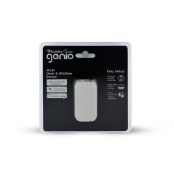
Device Name: Mirabella Genio Wi-Fi Door and Window Sensor
Device Type: Door and Window Sensor
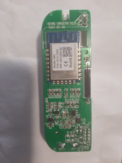
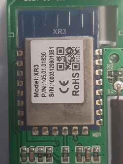
Device Chip: XR809 - XR3
Device Purchased: KMart - $27.00
Flashing of Main Chip
XR3 Module Datasheet
You will need to download phoenixMC.exe
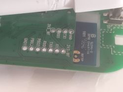
Step 1 - Connect your hardware to your UART device.
I used a SparkFun Serial Basic Breakout - CH340G to flash this module.
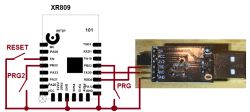
VCC - Power
TXD0 - RXD
RXD0 - TXD
PB02 - GND
PB03 - GND
EN - GND
GND - GND
You will need to have all these connections for the module to flash. Take your time making sure they all have a good connection or flashing will fail.
I use an ECU programming frame to flash my modules. This is the one I use
You will have to buy an extra set of probes as it only comes with 4 and you need 7.
Step 2 - Using phoenixMC.exe
Introduction to PhoenixMC
PhoenixMC is a flashing tool designed for the XR871 chip in a Windows environment that includes flash debugging functionality.
 The programming tool's main interface
1 - Serial Port Settings
A list box displays available serial ports. Select the serial ports that require firmware upgrade and click the refresh button if the serial port number changes. The upper drop-down box enables the selection of the serial port baud rate, and the chip only supports three baud rates: 9600, 115200, and 921600.
2 - Choose Firmware
Click the "Select Firmware" button, and a dialog box will appear to select the *.img file. The file path will be displayed in the edit box at the back, and the information of the image file will be displayed in the information box.
3 - General Settings
If there is a need to burn ETF firmware, select the "Burn ETF firmware" option, and a dialog box will appear for the user to select the required ETF firmware. Tick the "Verify after writing" option to read back the data for verification. If the communication protocol comes with verification, it is safe to uncheck this option. Checking "Update only modified files" will read the data of the block on the flash first, and if it is the same as the data to be programmed, the block will not be updated.
4 - Upgrade Firmware
Click the "Upgrade Firmware" button to perform the upgrade operation.
5 - Progress Bar and Status Prompt
The progress bar displays the current serial port programming progress. The status prompt bar indicates the current operation step. The progress bar displays green when the programming is successful, red when it fails, and blue when the programming is in progress.
6 - Stop
Click the "Stop" button to stop the current flash programming manually.
Using the program
1 - Check the serial port number and baud rate you need to program.
2 - Click "Select Firmware" to select the *.img file that needs to be upgraded, and view the file path and information displayed in the edit box and below the box, respectively.
3 - Select ETF firmware and verify the configuration, as required.
4 - Click "Upgrade Firmware" to perform the upgrade operation.
5 - Manually click to stop the operation, if necessary.
6 - The system will display "Update OK" or "error" to indicate the result of the upgrade.
Issues with flashing
Due to having so many pins to connect to you are bound to have issues. If it doesn't flash the first time check your connections and keep trying. It took me over 30 minutes to flash this device as I had to keep realigning the probes on the pins to make sure I had proper contact.
Configuration of Module
Unfortunately, I have not had success in configuring this module. I can get the device to show up on my network but when trying to connect to the website it fails to respond.
I have reflashed the device a few times with different versions of OpenBk but the results are all the same. I'm unsure what is happening and it could be something on the device is blocking the chip from loading or an error in the uploading of the firmware. Will keep tinkering and hopefully get a result. Will update this post if I have any success.
Device Type: Door and Window Sensor
Device Chip: XR809 - XR3
Device Purchased: KMart - $27.00


Flashing of Main Chip
XR3 Module Datasheet
You will need to download phoenixMC.exe
Step 1 - Connect your hardware to your UART device.
I used a SparkFun Serial Basic Breakout - CH340G to flash this module.

VCC - Power
TXD0 - RXD
RXD0 - TXD
PB02 - GND
PB03 - GND
EN - GND
GND - GND
You will need to have all these connections for the module to flash. Take your time making sure they all have a good connection or flashing will fail.
I use an ECU programming frame to flash my modules. This is the one I use
You will have to buy an extra set of probes as it only comes with 4 and you need 7.
Step 2 - Using phoenixMC.exe
Introduction to PhoenixMC
PhoenixMC is a flashing tool designed for the XR871 chip in a Windows environment that includes flash debugging functionality.
 The programming tool's main interface
1 - Serial Port Settings
A list box displays available serial ports. Select the serial ports that require firmware upgrade and click the refresh button if the serial port number changes. The upper drop-down box enables the selection of the serial port baud rate, and the chip only supports three baud rates: 9600, 115200, and 921600.
2 - Choose Firmware
Click the "Select Firmware" button, and a dialog box will appear to select the *.img file. The file path will be displayed in the edit box at the back, and the information of the image file will be displayed in the information box.
3 - General Settings
If there is a need to burn ETF firmware, select the "Burn ETF firmware" option, and a dialog box will appear for the user to select the required ETF firmware. Tick the "Verify after writing" option to read back the data for verification. If the communication protocol comes with verification, it is safe to uncheck this option. Checking "Update only modified files" will read the data of the block on the flash first, and if it is the same as the data to be programmed, the block will not be updated.
4 - Upgrade Firmware
Click the "Upgrade Firmware" button to perform the upgrade operation.
5 - Progress Bar and Status Prompt
The progress bar displays the current serial port programming progress. The status prompt bar indicates the current operation step. The progress bar displays green when the programming is successful, red when it fails, and blue when the programming is in progress.
6 - Stop
Click the "Stop" button to stop the current flash programming manually.
Using the program
1 - Check the serial port number and baud rate you need to program.
2 - Click "Select Firmware" to select the *.img file that needs to be upgraded, and view the file path and information displayed in the edit box and below the box, respectively.
3 - Select ETF firmware and verify the configuration, as required.
4 - Click "Upgrade Firmware" to perform the upgrade operation.
5 - Manually click to stop the operation, if necessary.
6 - The system will display "Update OK" or "error" to indicate the result of the upgrade.
Issues with flashing
Due to having so many pins to connect to you are bound to have issues. If it doesn't flash the first time check your connections and keep trying. It took me over 30 minutes to flash this device as I had to keep realigning the probes on the pins to make sure I had proper contact.
Configuration of Module
Unfortunately, I have not had success in configuring this module. I can get the device to show up on my network but when trying to connect to the website it fails to respond.
I have reflashed the device a few times with different versions of OpenBk but the results are all the same. I'm unsure what is happening and it could be something on the device is blocking the chip from loading or an error in the uploading of the firmware. Will keep tinkering and hopefully get a result. Will update this post if I have any success.
Cool? Ranking DIY


