logo elektroda
logo elektroda
X
logo elektroda

How to flash TR6260 with open source Tasmota/Esphome style firmware? Guide, pinout, booting

p.kaczmarek2 2913 28
ADVERTISEMENT
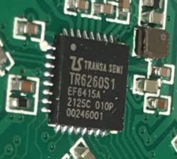
  • Close-up of the TR6260S1 microchip on a green PCB.
    Here's a detailed flashing guide for new TR6260 WiFi chips that can be found in some Tuya smart devices. TR6260 can be easily flashed and run free from the cloud, fully locally, without Tuya servers. This way you can easily pair TR6260 with Home Assistant via Home Assistant Discovery, add custom sensors (like DHT sensors family series or BMP280/BME280 etc), and run local scripts and automations.
    TR6260 is 32-bit, 2.4GHz WiFi-enabled SoC optimized for smart home/IoT applications, featuring 6x PWM, single ADC, flexible IO interfaces and 1MB of Flash.
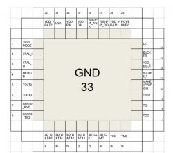
    TR6260 chip pinout diagram with pin labels.

    Where the TR6260 can be found?
    TR6260 have been so far observed in multiple devices, here are few of them:
    [TR6260S1 Transa Semi] Smart LED strip controller 144W 6A RGB, IR, firmware
    [TR6260S1/FL-M61 V2] WiFi Smart Switch how to change the firmware?
    ELM327 OBDII Scanner: Transa Semi ESWIN TR6260S1 MCU Details?
    [Flashing Tuya A5F-53F1-02 with TR6260S1 Chip
    You can also buy a development board with TR6260 called "Hi-Link HLK-M20", that can be ordered directly from China.

    Thanks to @insmod efforts in the development topic, those devices can be now flashed with OpenBeken

    HLK-M20 development board
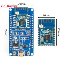
    This board can be easily found if you search for HLK-M20 Serial Port 2.4G WiFi Wireless Module IOT Serial to WiFi Transparent Transmission Low Power SDK M20 Development Board Kit. It's somewhat similiar to NodeMCU and other ESP boards. You can either buy just a module:
    Screenshot of an AliExpress listing for the HLK-M20 WiFi module.
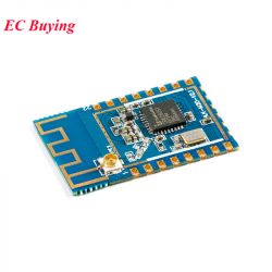
    TR6260S1 WiFi module on a PCB.
    or a full dev board, with module already soldered:
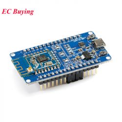
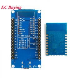
    Development board with TR6260 WiFi module on a white background. Image of two WiFi modules with the TR6260S1 microcontroller. Set of boards with a WiFi module and pin labels. Specifications of the HLK-M20 module with TR6260 chip.
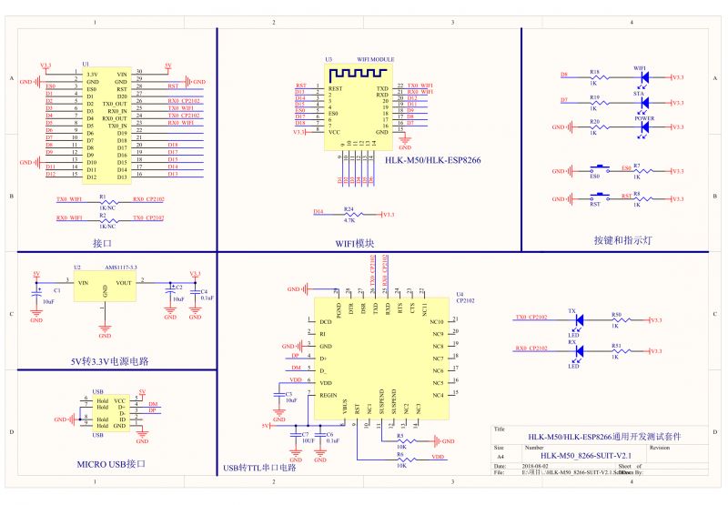
    Schematic:
    Schematic of HLK-M50/HLK-ESP8266 development board with WiFi module.
    In case of this board, everything needed to flash is already present, but if you're going to flash IoT device with TR6260, you will need to have your own USB to UART converter...

    What do I need to flash TR6260?
    To flash TR6260 found in IoT device, you need a classic USB to UART converter, similiar to ones used for ESP8266/ESP32/BK7231 flashing.
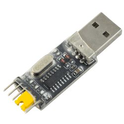
    USB to UART converter with plug and pin connectors.
    You will need to make some GPIO connections, so basic soldering skills are required.
    If you want to get a basic grasp of how firmware change process looks like, you can visit our Youtube channel:
    https://www.youtube.com/@elektrodacom
    We don't have TR6260 flashing video yet, but we have covered similiar chips in the past, like BK7231, so this might give you a basic overview of the procedure.


    Where to get UART flash tool?
    This is not ESP device, so esptool will not work. You will need to download utility called UTP. It can be found here:
    https://github.com/openshwprojects/FlashTools/tree/main/TransaSemi-ESWIN
    Alternate download/TS info pack:
    https://github.com/divadiow/TR6260/tree/main/UTP%20Flash%20Tool
    Here's English translation of UTP gui:
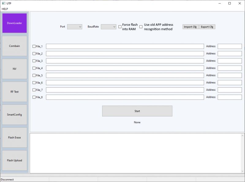
    UTP software interface for flashing TR6260 chips
    Translation of the partition table layout:
    https://obrazki.elektroda.pl/5232196400_1732140400.png
    And please note that restore of factory backup appears to require the file be split. eg: https://www.elektroda.com/rtvforum/topic4091587.html#21336099
    Now, let's focus on read and write procedures for flash...


    How to prepare connections and make TR6260 flash dump?
    In the case of the TR6260S1-based Hi-Link HLK-M20 module, which can be used as a template for any TR6260S1 device, a backup of the factory firmware can be achieved as follows:
    GPIO14/TOUT2 needs to be grounded at power-on. Like LN882H this needs to be before power to USB-TTL. Just resetting the device (RST->GND) with GPIO14 grounded will bring it up in spi-flash boot mode, that being standard boot, NOT UART boot mode:
    Screenshot showing a console set to a baud rate of 57600 with messages entry BootRom and spi-flash boot mode.
    If you're watching TX then the correct procedure will give this output:
    Fragment of a terminal window displaying boot mode messages with a selected baud rate of 57600.
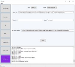
    then configure the UTP program as follows, using the boot_nocrc.bin from the same zip file. The flash is 1mb so length is 0x100000
    PC Local Filepath is just where you want to save the file
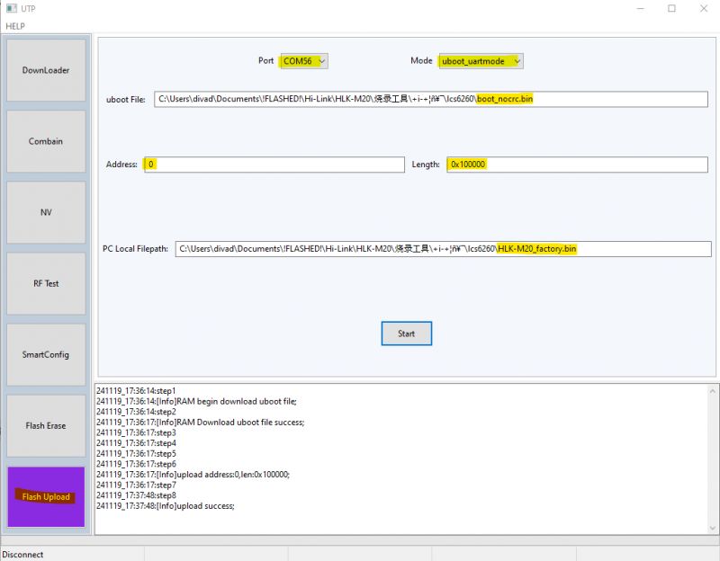
    Screenshot of the UTP application showing flash upload settings.
    It takes 2-3 mins and it may look like it has stalled.
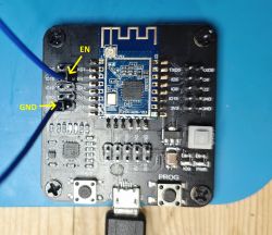
    On the HLK-M20 module GPIO14/TOUT2 pad is the location of EN on ESP-12F, so if using an ESP universal adaptor it's just a case of grounding EN header.
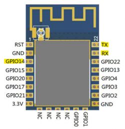
    Diagram of an electronic module with highlighted pins HLK-M20 development board with EN and GND connection points marked.
    If successful, the resultant backup file will be exactly 1,048,576 bytes.


    How to flash new firmware to TR6260?
    Before proceeding, make sure that you have a backup of factory flash. Once you are sure that everything is backed up, it's time to proceed with flashing.
    Ground GPIO14/TOUT2 as shown in the backup procedure and power-on the device
    Set appropriate COM port for your setup and a baud rate. Perhaps start at 921600 baud but reduce if there are issues with stability or connecting at all.
    Download the latest OpenTR6260_xxxx.bin firmware from the releases page.
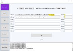
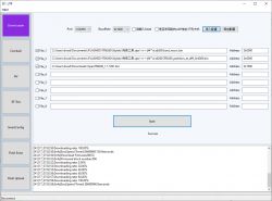
    Using the partition binaries alongside the UTP program in the zip, configure your file list on the downloader tab to resemble this:
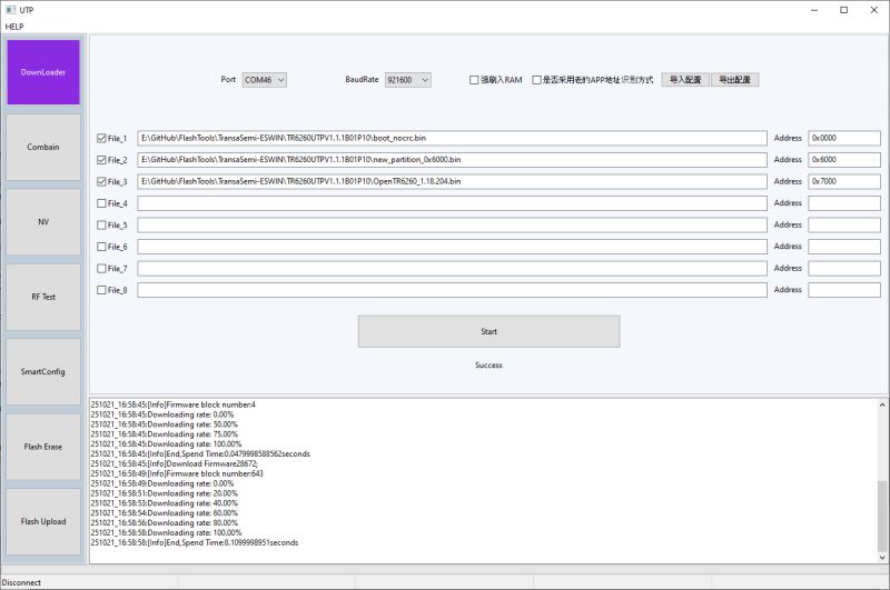
    Screenshot of the UTP tool used for flashing TR6260 chips.
    That being:
    File_1 : boot_nocrc.bin | Address: 0x0000
    File_2 : TR6260_partition_at_diff_0x6000.bin | Address: 0x6000
    File_3: OpenTR6260_xxxx.bin | Address: 0x7000
    File_4: IGNORE IT, no longer needed.
    Click Start.
    On completion, power-off and remove GPIO14/TOUT2 from ground. Power on the device and you should see it broadcast an AP like this
    Wireless network interface OpenTR6260 visible on the screen.
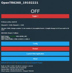
    Connect to the AP (no password required). When connected browse to 192.168.4.1 where you can configure OpenBK as normal.
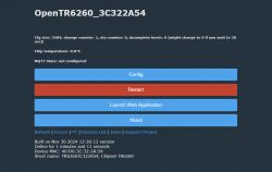
    OpenTR6260 user interface with configuration information and buttons

    For the steps taken on a real TR6260S1 device, where contacts are not so easily accessed as they are on a module, see this post regarding two flavours of ELM327 OBDII car code reader.

    Flashing with universal breakout board
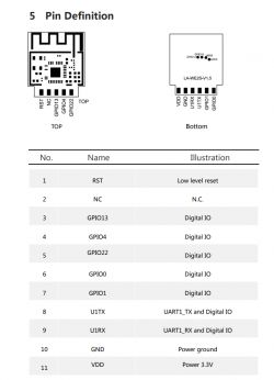
    HLK-M20 boards have pinout similiar to ESP12F/TYWE3S/CB3S/WB3S/etc, so they can fit to universal ESP breakout. Here is pin mapping for such board:
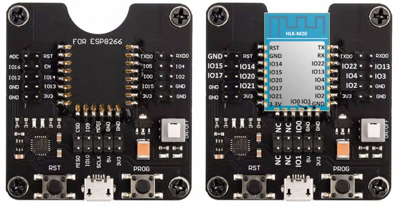
    HLK-M20 development board with TR6260 chip
    The following board has been already covered in another topic, see here:
    Programming ESP12/TYWE3S/CB3S/WB3S/etc. without soldering - solderless motherboard


    OpenTR6260 demo - DHT11 sensor
    OpenBeken port for TR6260 supports DHT11, which can be configured just like we've shown on our "Weather station" video for W600:


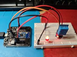
    Sample connection:
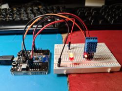
    Development board with a WiFi module and sensor connected to a breadboard with an LED. Development board with WiFi module and DHT11 sensor on a breadboard
    Video presentation - there is also a LED on Rel pin, so clicking button toggles it as expected. The read humidity and temperature is also visible on the main page as expected.


    OpenTR6260 demo - DME280 sensor
    BME280/BMP280 is also supported. For that, you need to create autoexec.bat with script:
    
    //startDriver BMPI2C [CLK] [DATA] [ChannelForTemp] [ChannelForPressure] [ChannelForHumidity] [Addr]
    startdriver bmpi2c 0 1 2 3 4
    

    If driver is missing, make sure that it is included in build - check obk_config.h.
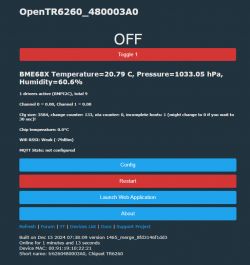
    OpenTR6260 configuration interface with temperature, pressure, and humidity details.
    Video presentation:


    Some extra information
    -TR6260S1 has some variations: https://www.elektroda.com/rtvforum/topic3965929-30.html#21315543
    -we've put all the known resources I have for TR6260 here inc all datasheets: https://github.com/divadiow/TR6260

    Summary
    TR6260 can now be flashed via UART with OBK port. OBK build for TR6260 can be customized with our online builds, you can also create a custom driver for that in such way. Thanks to that, your TR6260 devices can now work cloud-free and be paired with Home Assistant!
    Special thanks for @divadiow for researching/flashing and @insmod for porting.
    Hopefully soon we'll get ported to next platforms as well.

    Cool? Ranking DIY
    Helpful post? Buy me a coffee.
    About Author
    p.kaczmarek2
    Moderator Smart Home
    Offline 
    p.kaczmarek2 wrote 11952 posts with rating 9992, helped 572 times. Been with us since 2014 year.
  • ADVERTISEMENT
  • Helpful post
    #2 21353666
    divadiow
    Level 34  
    p.kaczmarek2 wrote:
    File_4: IGNORE IT, no longer needed.


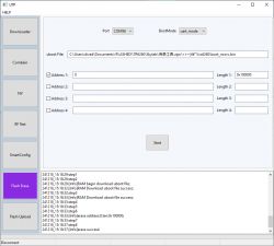
    I didn't consider dropping this file to determine the effect. To see what was at FB000 after flashing without the skylab_user_nv_0xFB000_PSM_by_Oliver.bin file selected, I first erased the whole flash. This was done as follows with TOUT2/GPIO14 grounded:

    Screenshot of UTP software with Flash Erase option selected.

    then flash again fresh

    Screenshot of Flashing Software with several binary files selected.

    boot OBK, join to wifi. then read the whole flash to file

    Screenshot of a software flashing program with flash settings and log.

    then compare from FB000 of the OBK backup to the start of skylab_user_nv_0xFB000_PSM_by_Oliver.bin in HxD

    Nothing
    Comparison of two binary file contents in a hex editor.
  • #3 21358543
    insmod
    Level 24  
    Another ESWIN module, the ECR6600. Tuya modules, based on this chip are AXY series, like AXY3L, AXY2S etc.
    Skylab WG236, which they claim is ECR6600 based, can be bought here: https://www.aliexpress.com/item/1005004281075586.html 5pcs, 14.5$ + ~8$ shipping.
    SDK: https://github.com/NonPIayerCharacter/ecr6600
    Readme in the sdk mentions tr6260, but it seems its support was cut out at some point.
    A little too pricey to me for a module that i won't use, but i may eventually buy it.
  • #4 21358612
    p.kaczmarek2
    Moderator Smart Home
    What's there? A module image flashes for a second and then I get "not available in my country". I can't view this offer.

    Btw, some devices can be bought cheaper if you're creating a new aliexpress account. For example, BK7238:
    Image of a NiceMCU WB3S ch340c development module with BK7238 chip on AliExpress.
    Helpful post? Buy me a coffee.
  • ADVERTISEMENT
  • #6 21358789
    divadiow
    Level 34  
    rip-off.

    Some other options maybe:

    Screenshot of the Superbuy website featuring BL-LINK WiFi modules. Screenshot from Superbuy site showing wireless module BL-M6600XS1 priced at $1.18 from Guangdong warehouse.

    no welcome deal on those Skylabs on Ali for me
    IoT electronic module with WiFi6 and Bluetooth interface displayed on an AliExpress page at a promotional price of £21.39.
  • #7 21361629
    p.kaczmarek2
    Moderator Smart Home
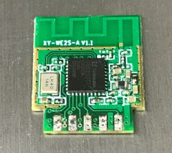
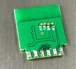
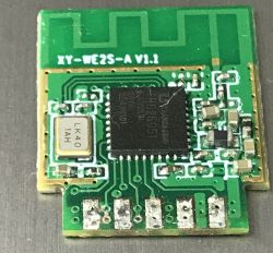
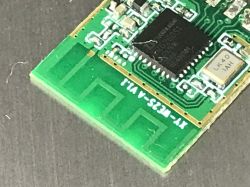
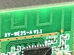
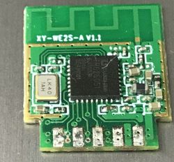
    I've found this module. Some reader must have sent it to me.
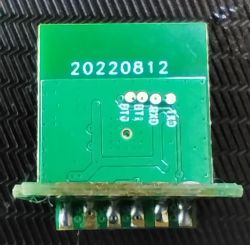
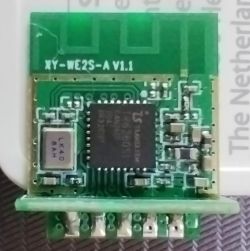
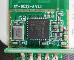
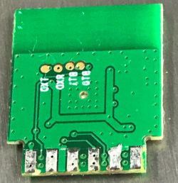
    Image of a green electronic module labeled XY-WE2S-A V1.1. Close-up of a green electronic module XY-WE2S-A V1.1 with visible tracks and soldering points. Close-up of an electronic module labeled XY-WE2S-A V1.1 with visible components and traces. Close-up of an electronic board labeled XY-WE2S-A V1.1.
    XY-WE2S-A V1.1
    Hmm https://www.elektroda.com/rtvforum/find.php?q=XY-WE2S-A+V1.1
    Anyone has any info? If not, I will have to try tracing the tracks...
    Helpful post? Buy me a coffee.
  • ADVERTISEMENT
  • #10 21367072
    divadiow
    Level 34  
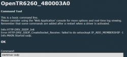
    SSDP on TR6260 observation
    Command tool interface with SSDP error messages.
    Code: Text
    Log in, to see the code
  • #11 21367078
    p.kaczmarek2
    Moderator Smart Home
    We need to enable multicast in LWIP like we did on Beken

    Added after 1 [minutes]:

    https://github.com/openshwprojects/OpenBK7231...mmit/b0f232db5f17b3ac558580767a677f2a2ee6d488
    Helpful post? Buy me a coffee.
  • #13 21367101
    divadiow
    Level 34  
    just saw you make that. was looking for the TR6260 SDK in openshwprojects initially :)

    Added after 21 [minutes]:

    File icon with the name OpenTR6260_480003A0.

    Code: Text
    Log in, to see the code


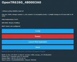
    OpenTR6260 user interface with system status information

    Added after 1 [minutes]:

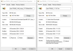
    Properties windows for two binary files displayed in the HxD hex editor.

    Added after 9 [minutes]:

    maybe already tested, but here's WEMO success anyway. Alexa discovers successfully.

    Code: Text
    Log in, to see the code


    Screenshot from an app showing a file named OpenTR6260_480003A0 labeled as Recently added.

    Added after 11 [minutes]:

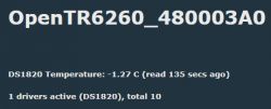
    Display of OpenTR6260 system with DS1820 sensor temperature.

    DS18B20 unchanged. I'm just refreshing my memory on what is working and what isn't right now

    Added after 3 [hours] 25 [minutes]:

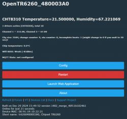
    Screenshot of the user interface for the OpenTR6260 device with temperature and humidity information. Properties windows of two BIN files in HxD Hex Editor.

    Added after 1 [hours] 32 [minutes]:

    what's the deal with the SHT3X driver not being definable as ENABLE_DRIVER_SHT3X in obk_config.h?

    Added after 53 [seconds]:

    https://github.com/openshwprojects/OpenBK7231...mits/8a6a9907bf37ec8c4ffad5cad8656bdb10a761c3
  • Helpful post
    #15 21405320
    morgan_flint
    Level 14  
    Flashing module XY-WE2S-A

    Although almost all of the info is already included in some posts in this other thread (read from this post), I think it's good to order it a bit and put it here in the flashing thread.

    First of all, some photos of the module (mine has a 90º adapter that has the advantage of including labels of the pinout in the silkscreen):

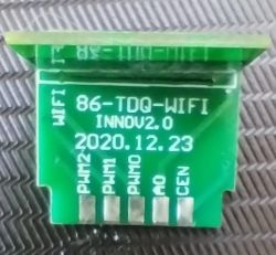
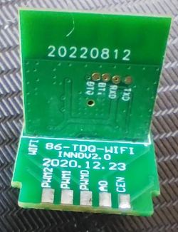
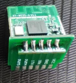
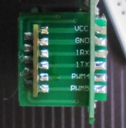
    XY-WE2S-A module with pin labels on the side Bottom side of module XY-WE2S-A, showing pads and pin labels. XY-WE2S-A module with visible pins. View of the bottom side of the module with pin labeling and production date. XY-WE2S-A V1.1 module with visible components and integrated circuit. XY-WE2S-A module with TR6260S1 chip Side view of the XY-WE2S-A module showing pins: VCC, GND, 1RX, 1TX, PWM4, PWM5.

    Three more pictures, borrowed from this post, that I edited to help me to trace the tracks to find the pinout:
    Image of the bottom side of the XY-WE2S-A module with visible pinout. Close-up of electronic module XY-WE2S-A V1.1 with visible components and traces. XY-WE2S-A V1.1 module with visible electronic components
    (the photo of the bottom side is mirrored to help match vias from the top layer)

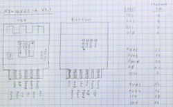
    The pinout and the correspondence between chip pins and module pads:
    Sketch of the pin layout for the XY-WE2S-A V1.1 module

    Unfortunately, the chip's pinout doesn't coincide with any of the datasheets or images posted in this forum! @divadiow also encountered this problem with HLK-M20 module, as he explained here. This table shows the differences between the datasheets and the "real" pinout of the chip in our modules:
    LABELIC PIN TR6260S1 datasheetTR6260 datasheetdivadiowReal Pin
    TX09 UART0_RXD SD_DATA0TXUART0_TXD
    RX08 TOUT3 UART0_TXDRXUART0_RXD
    BT1 7 TOUT2UART0_RXD-TOUT3
    BT0 6WAKE_UPTOUT3IO14TOUT2
     -10UART0_TXDSD_DATA1-?
    PWM221VDD1P2_1VDD1P2_1-GPIO22
    PWM119TRSTTRST-GPIO4
    PWM020GPIO13GPIO13-GPIO13
    A0not connected----
    CEN4TEST MODERESETB-RESETB
    PWM515TCKTCK-TCK-GPIO0
    PWM416TMSTMS-TMS-GPIO1
    ITX18TDITDI-TDI-GPIO3
    IRX17TDOTDO-TDO-GPIO2


    Maybe somebody here can find a TR6260S1 datasheet that is consistent with the "real" pinout... I've tried, unsuccesfully.

    So, to read or flash the module, we need to use the pads at the bottom side of the PCB, and connect those labeled TXD and RXD to USB to serial adapter's RXD and TXD, respectively. BT0 should be connected to GND, to set the chip in UART boot mode (as specified in the first post). Of course, VCC and GND should be connected to 3.3V and GND in the USB to serial adapter (which should be prepared for 3.3V levels at TXD and RXD). In my case, I prefer to connect VCC the last after plugging the USB to serial adapter to the PC.

    The rest of the backup/flashing procedure is as described in the first post. Many thanks to @p.kaczmarek2!!

    BTW, to have a correct log of the serial output when booting with BT0 grounded (to check it was booting in the correct mode), I had to set the baud rate to 58000, instead of the standard 57600, which showed strange characters:
    BT0 to GND - 57600 baud:
    L▒Y▒▒▒ Bo▒I▒▒)LsV▒▒▒сmode▒▒▒▒▒
    Le▒▒▒Boot▒▒)▒h▒▒▒ bo▒▒m▒V
    
    BT0 to GND - 58000 baud:
    Lentry BootRom
    Luart boot mode


    For the sake of curiosity, I tested all the possibilities for BT1-BT0. Here's the output, logged at 59000 baud:
    BT1 & BT0 isol:
    Lentry BootRom
    Lspi-flash boot mode
    
    BT1 GND & BT0 isol:
    Lentry BootRom
    Lsdio boot mode
    
    BT1 isol & BT0 GND:
    Lentry BootRom
    Luart boot mode
    
    BT1 & BT0 GND:
    Lentry BootRom
    Lunsupport boot mode
    Lbootrom startup err


    EDIT: Deleted the first table, redundant with the second one were I added more info and adding OBK logs and the final configuration

    This is the output at the serial port after flashing OBK:
    ▒f▒▒`▒▒▒▒▒▒`▒f▒▒▒▒``▒f▒▒x▒▒▒▒▒▒▒`▒▒▒`fx▒▒[00:00:00.018]EasyFlash V4.0.0 is initialize success.
    this is not eco chip, chip type: 2
    
    No 1. Task Name(LMAC Task) Handle(2106292) Added to Stack Trace
    0x240200 0x240400 0x240600 0x240800 0x240a00 0x240c00 0x240e00 0x241000 0x241200 0x241400 0x241600 0x241800 0x241a00 0x241c00 0x241e00 0x242000 0x242200 0x242400 0x242600 0x242800 0x242a00 0x242c00 0x242e00 0x243000 0x243200 0x243400 0x243600 0x243800 0x243a00 0x243c00 0x243e00 0x244000 mainldo_nv_flag=0 buck_nv_flag=0 chip_id=2  is_cp=0
    LMAC initialize success
    vif_id:0, scanning:false
    No 2. Task Name(wpa_supplicant) Handle(2129216) Added to Stack Trace
    [standalone_main, 152] task creation succeed!(0x207d40)
    wifi nv:ssid[XxxxxxXXxxx],pwd[xxxxxxxxxxx],bssid[70:2e:22:db:0c:56],channel[8],pmk[fa4e9e]
    wdt_not_start
    No 3. Task Name(IDLE) Handle(2123412) Added to Stack Trace
    No 4. Task Name(Tmr Svc) Handle(2128576) Added to Stack Trace
    wlif_init
    
    wlif_init
    
    vif_id:0, scanning:false
    wpa state:DISCON->INACT.
    wpa state:INACT->DISCON.
    wpa state:DISCON->INACT.
    wpa state:INACT->DISCON.
    vif[0],event[27]
    vif[0],event[27]
    vif[1],event[27]
    vif[1],event[27]
    SYSTEM_EVENT_WIFI_READY
    OK
    OK
    
    Entering initLog()...
    
    Commands registered!
    
    initLog() done!
    
    Info:MAIN:Main_Init_Before_Delay
    
    WiFI_SetMacAddress
    
    Main_Init_Before_Delay done


    Main_Init_Delay
    
    Warn:CFG:CFG_InitAndLoad: Correct config has been loaded with 16 changes count.
    
    Error:CMD:lfs is absent
    
    Info:GEN:PIN_SetupPin
    
    Main_Init_Delay done
    
    s pins have been set up.
    
    Info:MAIN:Main_Init_Before_Delay done
    
    Info:MAIN:Main_Init_Delay
    
    Info:MAIN:Main_Init_Delay done
    
    Info:MAIN:Main_Init_After_Delay
    
    Info:MAIN:Using SSID [MorganNet]
    
    Info:MAIN:Using Pass [tomasfernando]
    
    Info:HTTP:TCP server listening
    
    Info:MQTT:MQTT_RegisterCallback called for bT tr626019102221/ subT tr626019102221/+/set
    
    Info:MQTT:MQTT_RegisterCallback called for bT tr6260/ subT tr6260/+/set
    
    Info:MQTT:MQTT_RegisterCallback called for bT cmnd/tr626019102221/ subT cmnd/tr626019102221/+
    
    Info:MQTT:MQTT_RegisterCallback called for bT cmnd/tr6260/ subT cmnd/tr6260/+
    
    Info:MQTT:MQTT_RegisterCallback called for bT tr626019102221/ subT tr626019102221/+/get
    
    Info:CMD:CMD_StartScript: started @startup at the beginning
    
    Error:CMD:LFS_ReadFile: lfs is absent
    
    Info:CMD:CMD_StartScript: failed to get file autoexec.bat
    
    Info:MAIN:Main_Init_After_Delay done
    
    Info:MAIN:Time 1, idle 0/s, free 79936, MQTT 0(0), bWifi 0, secondsWithNoPing -1, socks 2/12
    
    Info:MAIN:Time 2, idle 0/s, free 79936, MQTT 0(0), bWifi 0, secondsWithNoPing -1, socks 2/12
    
    Info:MAIN:Time 3, idle 0/s, free 79936, MQTT 0(0), bWifi 0, secondsWithNoPing -1, socks 2/12
    
    Info:MAIN:Time 4, idle 0/s, free 79936, MQTT 0(0), bWifi 0, secondsWithNoPing -1, socks 2/12
    
    HAL_WiFi_SetupStatusCallbackHAL_ConnectToWiFiFAIL
    
    OK
    
    OK
    
    OK
    
    OK
    OK
    
    OK
    
    OK
    
    wpa state:DISCON->SCAN.
    vif_id:0, scanning:true
    Info:MAIN:Time 5, idle 0/s, free 79936, MQTT 0(0), bWifi 0, secondsWithNoPing -1, socks 2/12
    
    Info:MAIN:Registered for wifi chvif[0],event[27]
    anges
    
    Info:MAIN:Connecting to SSID [MorganNet]
    
    vif_id:0, scanning:false
    wpa state:SCAN->AUTH.
    vif[0],event[1]
    vif[0],event[27]
    wpa state:AUTH->ASSOC.
    ---set rate--0xff:0x0fff
    25 mcs: 255 rate:0xfff
    vif[0],event[27]
    wpa state:ASSOC->ASSOCIATED.
    wpa state:ASSOCIATED->HANDSHAKE.
    vif[0],event[27]
    vif[0],event[27]
    wpa state:HANDSHAKE->HANDSHAKE.
    wpa state:HANDSHAKE->GROUP_HANDSHAKE.
    wpa state:GROUP_HANDSHAKE->COMPLETED.
    vif[0],event[27]
    vif[0],event[27]
    vif[0],event[4]
    dhcpc start ok!
    Info:MAIN:Time 6, idle 0/s, free 78880, MQTT 0(0), bWifi 0, secondsWithNoPing -1, socks 2/12
    
    Info:MAIN:Boot complete time reached (5 seconds)
    
    Info:MAIN:Time 7, idle 0/s, free 78880, MQTT 0(0), bWifi 0, secondsWithNoPing -1, socks 2/12
    
    Info:MAIN:Time 8, idle 0/s, free 78880, MQTT 0(0), bWifi 0, secondsWithNoPing -1, socks 2/12
    
    Info:MAIN:Time 9, idle 0/s, free 78880, MQTT 0(0), bWifi 0, secondsWithNoPing -1, socks 2/12
    
    vif[0],event[8]
    sta ip: 192.168.1.143, mask: 255.255.255.0, gw: 192.168.1.1
    Info:MAIN:Main_OnWiFiStatusChange - WIFI_STA_CONNECTED - 4
    
    +--------------- net device info ------------+
    
    |netif type    : STA                         |
    
    Info:MAIN:Time 10, idle 0/s, free 78880, MQTT 0(0), bWifi 1, secondsWithNoPing -1, socks 2/12
    
    |netif ip      = 192.168.1.143               |
    
    |netif mask    = 255.255.255.0               |
    
    |netif gateway = 192.168.1.1                 |
    
    |netif mac     : [00:91:19:10:22:21]         |
    
    +--------------------------------------------+
    
    Info:MAIN:Time 11, idle 0/s, free 78880, MQTT 0(0), bWifi 1, secondsWithNoPing -1, socks 2/12
    
    Info:MQTT:mqtt_host empty, not starting mqtt
    
    Info:MAIN:Time 12, idle 0/s, free 76264, MQTT 0(1), bWifi 1, secondsWithNoPing -1, socks 2/12
    
    Info:MAIN:Time 13, idle 0/s, free 76264, MQTT 0(1), bWifi 1, secondsWithNoPing -1, socks 2/12
    
    Info:MAIN:Time 14, idle 0/s, free 76264, MQTT 0(1), bWifi 1, secondsWithNoPing -1, socks 2/12
    
    Info:MAIN:Time 15, idle 0/s, free 76264, MQTT 0(1), bWifi 1, secondsWithNoPing -1, socks 2/12
    
    Info:MAIN:Time 16, idle 0/s, free 76264, MQTT 0(1), bWifi 1, secondsWithNoPing -1, socks 2/12
    
    Info:MAIN:Time 17, idle 0/s, free 76264, MQTT 0(1), bWifi 1, secondsWithNoPing -1, socks 2/12
    
    Info:MAIN:Time 18, idle 0/s, free 76264, MQTT 0(1), bWifi 1, secondsWithNoPing -1, socks 2/12
    
    Info:MAIN:Time 19, idle 0/s, free 76264, MQTT 0(1), bWifi 1, secondsWithNoPing -1, socks 2/12
    
    +--------------- net device info ------------+
    
    |netif type    : STA                         |
    
    Info:MAIN:Time 20, idle 0/s, free 76264, MQTT 0(1), bWifi 1, secondsWithNoPing -1, socks 2/12
    
    |netif ip      = 192.168.1.143               |
    
    |netif mask    = 255.255.255.0               |
    
    |netif gateway = 192.168.1.1                 |
    
    |netif mac     : [00:91:19:10:22:21]         |
    
    +--------------------------------------------+
    
    Info:MAIN:Time 21, idle 0/s, free 76264, MQTT 0(1), bWifi 1, secondsWithNoPing -1, socks 2/12
    
    Info:MAIN:Time 22, idle 0/s, free 76264, MQTT 0(1), bWifi 1, secondsWithNoPing -1, socks 2/12
    
    Info:MAIN:Time 23, idle 0/s, free 76264, MQTT 0(1), bWifi 1, secondsWithNoPing -1, socks 2/12
    
    Info:MAIN:Time 24, idle 0/s, free 76264, MQTT 0(1), bWifi 1, secondsWithNoPing -1, socks 2/12
    
    Info:MAIN:Time 25, idle 0/s, free 76264, MQTT 0(1), bWifi 1, secondsWithNoPing -1, socks 2/12
    
    Info:MAIN:Time 26, idle 0/s, free 76264, MQTT 0(1), bWifi 1, secondsWithNoPing -1, socks 2/12
    
    Info:MAIN:Time 27, idle 0/s, free 76016, MQTT 0(1), bWifi 1, secondsWithNoPing -1, socks 2/12
    
    Info:MQTT:mqtt_host empty, not starting mqtt
    
    Info:MAIN:Time 28, idle 0/s, free 58392, MQTT 0(2), bWifi 1, secondsWithNoPing -1, socks 3/12
    
    Info:MAIN:Time 29, idle 0/s, free 58608, MQTT 0(2), bWifi 1, secondsWithNoPing -1, socks 3/12
    
    +--------------- net device info ------------+
    
    |netif type    : STA                         |
    
    Info:MAIN:Time 30, idle 0/s, free 67192, MQTT 0(2), bWifi 1, secondsWithNoPing -1, socks 2/12
    
    |netif ip      = 192.168.1.143               |
    
    |netif mask    = 255.255.255.0               |
    
    |netif gateway = 192.168.1.1                 |
    
    |netif mac     : [00:91:19:10:22:21]         |
    
    +--------------------------------------------+
    
    Info:MAIN:Time 31, idle 0/s, free 63848, MQTT 0(2), bWifi 1, secondsWithNoPing -1, socks 3/12
    
    Info:MAIN:Time 32, idle 0/s, free 55368, MQTT 0(2), bWifi 1, secondsWithNoPing -1, socks 3/12
    
    Info:MQTT:Channel has changed! Publishing 1 to channel 1
    
    Info:MAIN:Time 33, idle 0/s, free 49544, MQTT 0(2), bWifi 1, secondsWithNoPing -1, socks 3/12
    
    Info:MQTT:Channel has changed! Publishing 0 to channel 1
    
    Info:MAIN:Time 34, idle 0/s, free 59048, MQTT 0(2), bWifi 1, secondsWithNoPing -1, socks 2/12
    
    Info:MAIN:Time 35, idle 0/s, free 75456, MQTT 0(2), bWifi 1, secondsWithNoPing -1, socks 2/12
    
    Info:MAIN:Time 36, idle 0/s, free 74704, MQTT 0(2), bWifi 1, secondsWithNoPing -1, socks 2/12
    
    Info:MAIN:Time 37, idle 0/s, free 74920, MQTT 0(2), bWifi 1, secondsWithNoPing -1, socks 2/12
    
    Info:MAIN:Time 38, idle 0/s, free 75792, MQTT 0(2), bWifi 1, secondsWithNoPing -1, socks 2/12
    
    Info:MAIN:Time 39, idle 0/s, free 75792, MQTT 0(2), bWifi 1, secondsWithNoPing -1, socks 2/12
    
    +--------------- net device info ------------+
    
    |netif type    : STA                         |
    
    Info:MAIN:Time 40, idle 0/s, free 75792, MQTT 0(2), bWifi 1, secondsWithNoPing -1, socks 2/12
    
    |netif ip      = 192.168.1.143               |
    
    |netif mask    = 255.255.255.0               |
    
    |netif gateway = 192.168.1.1                 |
    
    |netif mac     : [00:91:19:10:22:21]         |
    
    +--------------------------------------------+
    
    Info:MAIN:Time 41, idle 0/s, free 75664, MQTT 0(2), bWifi 1, secondsWithNoPing -1, socks 2/12
    
    Info:GEN:2 Button_OnInitialPressDown
    
    Info:GEN:2 key_short_press
    
    Info:MQTT:Channel has changed! Publishing 1 to channel 1
    
    Info:MAIN:Time 42, idle 0/s, free 75792, MQTT 0(2), bWifi 1, secondsWithNoPing -1, socks 2/12
    
    Info:MAIN:Time 43, idle 0/s, free 75792, MQTT 0(2), bWifi 1, secondsWithNoPing -1, socks 2/12
    
    Info:MQTT:mqtt_host empty, not starting mqtt
    
    Info:MAIN:Time 44, idle 0/s, free 75576, MQTT 0(3), bWifi 1, secondsWithNoPing -1, socks 2/12
    
    Info:MAIN:Time 45, idle 0/s, free 75792, MQTT 0(3), bWifi 1, secondsWithNoPing -1, socks 2/12
    
    Info:MAIN:Time 46, idle 0/s, free 75792, MQTT 0(3), bWifi 1, secondsWithNoPing -1, socks 2/12
    
    Info:MAIN:Time 47, idle 0/s, free 75792, MQTT 0(3), bWifi 1, secondsWithNoPing -1, socks 2/12
    
    Info:MQTT:Channel has changed! Publishing 0 to channel 1
    
    Info:MAIN:Time 48, idle 0/s, free 67304, MQTT 0(3), bWifi 1, secondsWithNoPing -1, socks 2/12
    
    Info:MAIN:Time 49, idle 0/s, free 75792, MQTT 0(3), bWifi 1, secondsWithNoPing -1, socks 2/12
    
    +--------------- net device info ------------+
    
    |netif type    : STA                         |
    
    |netif ip      = 192.168.1.143               |
    
    Info:MAIN:Time 50, idle 0/s, free 75792, MQTT 0(3), bWifi 1, secondsWithNoPing -1, socks 2/12
    
    |netif mask    = 255.255.255.0               |
    
    |netif gateway = 192.168.1.1                 |
    
    |netif mac     : [00:91:19:10:22:21]         |
    
    +--------------------------------------------+
    
    Info:MAIN:Time 51, idle 0/s, free 75792, MQTT 0(3), bWifi 1, secondsWithNoPing -1, socks 2/12
    
    Info:MAIN:Time 52, idle 0/s, free 75792, MQTT 0(3), bWifi 1, secondsWithNoPing -1, socks 2/12
    
    Info:MAIN:Time 53, idle 0/s, free 75792, MQTT 0(3), bWifi 1, secondsWithNoPing -1, socks 2/12
    
    Info:MAIN:Time 54, idle 0/s, free 76008, MQTT 0(3), bWifi 1, secondsWithNoPing -1, socks 2/12
    
    Info:MAIN:Time 55, idle 0/s, free 75792, MQTT 0(3), bWifi 1, secondsWithNoPing -1, socks 2/12
    
    Info:MAIN:Time 56, idle 0/s, free 76008, MQTT 0(3), bWifi 1, secondsWithNoPing -1, socks 2/12
    
    Info:MAIN:Time 57, idle 0/s, free 76008, MQTT 0(3), bWifi 1, secondsWithNoPing -1, socks 2/12
    
    Info:MAIN:Time 58, idle 0/s, free 76008, MQTT 0(3), bWifi 1, secondsWithNoPing -1, socks 2/12
    
    Info:MAIN:Time 59, idle 0/s, free 76008, MQTT 0(3), bWifi 1, secondsWithNoPing -1, socks 2/12
    
    +--------------- net device info ------------+
    
    |netif type    : STA                         |
    
    |netif ip      = 192.168.1.143               |
    
    Info:MQTT:mqtt_host empty, not starting mqtt
    
    Info:MAIN:Time 60, idle 0/s, free 76008, MQTT 0(4), bWifi 1, secondsWithNoPing -1|netif mask    = 255.255.255.0               |
    
    |netif gateway = 192.168.1.1                 |
    
    , socks 2/12
    
    |netif mac     : [00:91:19:10:22:21]         |
    
    +--------------------------------------------+
    
    
    [0]standalone:Info:MAIN:Time 61, idle 0/s, free 75872, MQTT 0(4), bWifi 1, secondsWithNoPing -1, socks 2/12
    
    Info:MAIN:Time 62, idle 0/s, free 75872, MQTT 0(4), bWifi 1, secondsWithNoPing -1, socks 2/12
    
    Info:MAIN:Time 63, idle 0/s, free 75872, MQTT 0(4), bWifi 1, secondsWithNoPing -1, socks 2/12
    
    k
    sys_task not initialized yet
    [4]standalone:Info:MQTT:mqtt_host empty, not starting mqtt
    
    Info:MAIN:Time 92, idle 0/s, free 74776, MQTT 0(6), bWifi 1, secondsWithNoPing 23, socks 2/12
    
    Info:MAIN:Time 93, idle 0/s, free 74920, MQTT 0(6), bWifi 1, secondsWithNoPing 24, socks 2/12
    
    Info:MAIN:Time 94, idle 0/s, free 74560, MQTT 0(6), bWifi 1, secondsWithNoPing 25, socks 2/12
    
    Info:MAIN:Time 95, idle 0/s, free 74776, MQTT 0(6), bWifi 1, secondsWithNoPing 26, socks 2/12
    
    Info:MAIN:Time 96, idle 0/s, free 74424, MQTT 0(6), bWifi 1, secondsWithNoPing 27, socks 2/12
    
    Info:MAIN:Time 97, idle 0/s, free 72640, MQTT 0(6), bWifi 1, secondsWithNoPing 28, socks 3/12
    
    Info:MAIN:Time 98, idle 0/s, free 74784, MQTT 0(6), bWifi 1, secondsWithNoPing 29, socks 2/12
    
    Info:MAIN:Time 99, idle 0/s, free 74424, MQTT 0(6), bWifi 1, secondsWithNoPing 30, socks 2/12
    
    +--------------- net device info ------------+
    
    |netif type    : STA                         |
    
    Info:MAIN:Time 100, idle 0/s, free 74784, MQTT 0(6), bWifi 1, secondsWithNoPing 31, socks 2/12
    
    |netif ip      = 192.168.1.143               |
    
    |netif mask    = 255.255.255.0               |
    
    |netif gateway = 192.168.1.1                 |
    
    |netif mac     : [00:91:19:10:22:21]         |
    
    +--------------------------------------------+
    
    Info:MAIN:Time 101, idle 0/s, free 74440, MQTT 0(6), bWifi 1, secondsWithNoPing 32, socks 2/12
    
    Info:MAIN:Time 102, idle 0/s, free 74784, MQTT 0(6), bWifi 1, secondsWithNoPing 33, socks 2/12
    
    Info:MAIN:Time 103, idle 0/s, free 74440, MQTT 0(6), bWifi 1, secondsWithNoPing 34, socks 2/12
    
    Info:MAIN:Time 104, idle 0/s, free 74784, MQTT 0(6), bWifi 1, secondsWithNoPing 35, socks 2/12
    
    Info:MAIN:Time 105, idle 0/s, free 74440, MQTT 0(6), bWifi 1, secondsWithNoPing 36, socks 2/12
    
    Info:MAIN:Time 106, idle 0/s, free 74784, MQTT 0(6), bWifi 1, secondsWithNoPing 37, socks 2/12
    
    Info:MAIN:Time 107, idle 0/s, free 74440, MQTT 0(6), bWifi 1, secondsWithNoPing 38, socks 2/12
    
    Info:MQTT:mqtt_host empty, not starting mqtt
    
    Info:MAIN:Time 108, idle 0/s, free 74784, MQTT 0(7), bWifi 1, secondsWithNoPing 39, socks 2/12
    
    Info:MAIN:Time 109, idle 0/s, free 74568, MQTT 0(7), bWifi 1, secondsWithNoPing 40, socks 2/12
    
    +--------------- net device info ------------+
    
    |netif type    : STA                         |
    
    Info:MAIN:Time 110, idle 0/s, free 74440, MQTT 0(7), bWifi 1, secondsWithNoPing 41, socks 2/12
    
    |netif ip      = 192.168.1.143               |
    
    |netif mask    = 255.255.255.0               |
    
    |netif gateway = 192.168.1.1                 |
    
    |netif mac     : [00:91:19:10:22:21]         |
    
    +--------------------------------------------+
    
    Info:MAIN:Time 111, idle 0/s, free 74784, MQTT 0(7), bWifi 1, secondsWithNoPing 42, socks 2/12
    
    Info:MAIN:Time 112, idle 0/s, free 75872, MQTT 0(7), bWifi 1, secondsWithNoPing 43, socks 2/12
    
    Info:MAIN:Time 113, idle 0/s, free 74776, MQTT 0(7), bWifi 1, secondsWithNoPing 44, socks 2/12


    And the template for the device:
    Code: JSON
    Log in, to see the code


    Note that, with the present version of OBK at the time of writting, GPIO13, which commands the relay, doesn't work!
    The modification at this pull request is needed.
    (already merged)
  • #16 21405622
    micbanand
    Level 5  
    p.kaczmarek2 wrote:
    I've found this module. Some reader must have sent it to me.
    Image of a green electronic module labeled XY-WE2S-A V1.1. Close-up of a green electronic module XY-WE2S-A V1.1 with visible tracks and soldering points. Close-up of an electronic module labeled XY-WE2S-A V1.1 with visible components and traces. Close-up of an electronic board labeled XY-WE2S-A V1.1.
    XY-WE2S-A V1.1
    Hmm https://www.elektroda.com/rtvforum/find.php?q=XY-WE2S-A+V1.1
    Anyone has any info? If not, I will have to try tracing the tracks...

    it was me who send you 2 of them :)
    is there a solution for it know.
    Gues I have to read upon this new thread
  • #17 21405697
    divadiow
    Level 34  
    micbanand wrote:
    me who send you 2 of them

    😀

    Do you have more to have a go dumping from?
  • #18 21406067
    micbanand
    Level 5  
    >>21405697 what do you mean?
    I bought 12 of them. and replaced the modules with esp02
  • #19 21406068
    divadiow
    Level 34  
    oh wow ok. 12. loads to play with!
  • #20 21407688
    divadiow
    Level 34  
    also worth mentioning that although I said about splitting the file here you can flash the whole backup from 0 as long as you also choose boot_nocrc.bin from 0 first

    Screenshot of a flash management program with visible file paths and port settings.

    with just the 1mb backup specified it'll fail with

    Code: Text
    Log in, to see the code
  • #21 21416923
    morgan_flint
    Level 14  
    divadiow wrote:
    also worth mentioning that although I said about splitting the file here you can flash the whole backup from 0 as long as you also choose boot_nocrc.bin from 0 first

    Yes, I can confirm that, that's the way I flashed my backup (provisionally) to the device after having tested the module with OBK
  • #22 21419873
    morgan_flint
    Level 14  
    I finally have the module mounted back in the device and working with OBK.

    I'll edit my previous post to add info of the final configuration and OBK logs

    Many thanks to @divadiow for his help (long conversation via PM), and to @insmod for pointing the modification in the code to get working the GPIO13 (that commands the relay).
  • ADVERTISEMENT
  • #23 21419915
    p.kaczmarek2
    Moderator Smart Home
    Good job, what is the state on the GPIO13 fix? I assume it should be merged to the main tree now? Can you point which PR is that?
    Helpful post? Buy me a coffee.
  • #24 21419919
    divadiow
    Level 34  
    https://github.com/openshwprojects/OpenBK7231T_App/pull/1526

    Added after 3 [minutes]:

    what does this mean for..

    Code: Text
    Log in, to see the code


    why are they not enabled? why those 3 disabled in SDK?

    Added after 15 [minutes]:

    divadiow wrote:
    why are they not enabled? why those 3 disabled in SDK?

    something specific for the LSC6260 module perhaps (SDK came from Skylab and was in LSC6260 folder) or what was developed for it. Maybe they should be enabled for general TR6260 use?

    Added after 3 [minutes]:

    >>21327639

    Quote:
    Very good job @insmod ! I need to get/find my TR fast, hopefully it didn't drown when my basement got flooded...


    did it die in the flood?
  • #25 21419965
    insmod
    Level 24  
    >>21419919
    16/17 can't be used as gpio at all.
    https://github.com/NonPIayerCharacter/OpenTR6...ee5218c21a598b9470194/drivers/hal_gpio.c#L123
    And there is no code to initialize them as gpio.
    Cursory glance reveals that gpio13/gpio17 are used for sleep/wake?
    And all pins, including 16/17 can be used in gpio_power_area_config, though i have no idea what that is.
    https://github.com/NonPIayerCharacter/OpenTR6...ee5218c21a598b9470194/drivers/hal_gpio.c#L615

    Added after 2 [minutes]:

    But, there are separate functions for them, gpio16_write, gpio17_write and gpio17_read. No gpio16_read.
  • #26 21421792
    morgan_flint
    Level 14  
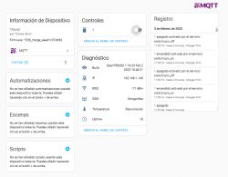
    I saw the PR is now merged, so I flashed the last official version and everything went well:

    Screenshot of OpenTR6260 interface displaying device information.

    I also configured MQTT to test it from Home Assistant, with good results:

    Screenshot of a user interface displaying information about the TR6260 device.
    I understand that the temperature is "unknown" because the sensor must be missing in this chip. If I remember well, it appeared before on the main OBK page but has already been removed. Shouldn't it be removed from MQTT as well?
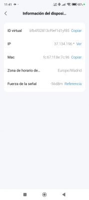
    Another question: Although the device is in the same room as my router, the WiFi signal appears to be very low. This doesn't happen with my other OBK devices. Could it be because of some kind of RF configuration (similar to that in Belken chips) that could have been lost in the flashing process? In this case: Could it be recovered from the initial backup?

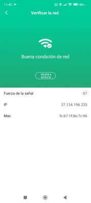
    EDIT: Just seen I hadn't really flashed the latest official release, as the screenshot still showed the merged one. I flashed OBK again (previous screenshot updated) after first flashing the original FW (full 1MB backup), to check if that corrected the WiFi signal strength issue, with no luck, as it continues to be weak (-71dBm) at 1.5 meters from the router. With the original FW, the RSSI in the same exact location was -56 - -57 dBm:

    Screenshot displaying device information, including ID, IP address, MAC, time zone, and WiFi signal strength. Screenshot of an app displaying WiFi signal strength, IP address, and MAC address.

    Has anybody else noticed this weakening of the signal strength?
  • #27 21426466
    morgan_flint
    Level 14  
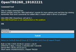
    @p.kaczmarek2 and/or @insmod, some more questions about OpenTR6260: I've seen here that PowerSave 1 is advisable in these "Smart switches" to avoid overloading the power supply. Is it also the case for those with TR6260?

    Also, regarding the issue with WiFi RSSI mentioned before, is there an explanation for that? Is that important? I mean, could it simply be a problem in the reported data, being WiFi connection still as good as with the original FW?

    Thank you very much in advance!

    EDIT: Sorry, this answers my first question:
    Screenshot of the OpenTR6260 interface indicating that PowerSave is not implemented.

Topic summary

The discussion focuses on flashing the TR6260 WiFi chip, commonly found in Tuya smart devices, with open-source firmware to enable local control without reliance on Tuya servers. Users share experiences and methods for flashing the chip, including pinout details, booting procedures, and troubleshooting issues related to WiFi signal strength and GPIO configurations. Various modules utilizing the TR6260, such as the XY-WE2S-A and ECR6600, are mentioned, along with links to SDKs and firmware backups. Participants also discuss the importance of enabling power-saving features and the implications of flashing on device performance.
Summary generated by the language model.
ADVERTISEMENT