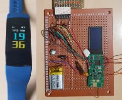
Recently, I presented the interior of a cheap smartband with a BT interface, a color display and several functions typical for this segment https://www.elektroda.pl/rtvforum/topic3975641.html. Now I will describe how to start programming this system.
The band is controlled by SoC DA14585 from Dialog (Renesas) with an ARM Cortex-M0 core. It has 96 kB of RAM and 64 kB of one-time programmable (OTP) memory. As it turned out, the system can be programmed, because it has an external FLASH memory connected via SPI. In addition, there are mini fields on the board for connecting the UART interface.
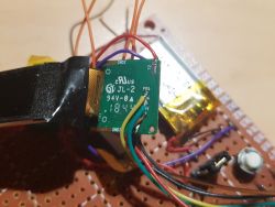
The discovery of the UART interface enabled me to establish communication and upload my own software using the programming tools provided by Renesas. The good news is that Renesas has released versions of these tools for Windows and Linux.
Tools and libraries useful for programming DL14585:
SmartSnippets™ Toolbox
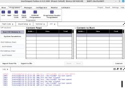
A set of tools enabling communication with the DA15855. It has a GUI but can be used from the command line.
SmartSnippets™ Studio
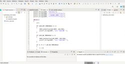
Renesas proprietary IDE, still under development, still a bit underdeveloped compared to Keil. Not essential, I prefer Keil in this application.
Both of the above tools can be downloaded from smartbond-development-tools
Guide to installing and using SmartSnippets um-b-057
Keil MDK 5.38
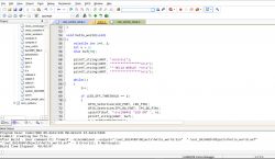
IDE for software development. Windows only version, I installed it on wine-8.0.1.
Download from Keil MDK , after registering and logging in.
Software Development Kit SDK6.0.18.1182.1 for DA1453x, DA14585/6
A set of libraries with sample programs.
Download from SDKs after logging in
USB-UART adapter
Necessarily on the FTDI chip, because the SmartSnippetsToolbox programmer does not recognize others :)
I do not describe the installation process because I did it on linux, it may be different on Windows.
Overall, the installation went without any problems. If something was missing, I just read the message and installed it, I think there is no point in describing it. Alternatively, if anyone wants to play and encounters a problem, feel free to ask questions.
Preparation for programming
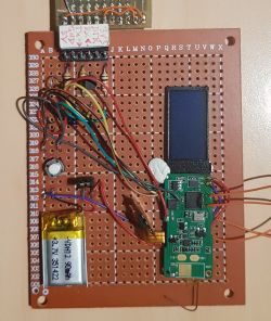
The board, after being removed from the headband housing, is quite bulky, the connections are made of thin wires and tapes, so it was necessary to place it on a larger "development" board.
I used a universal board for this, on which I placed some electronics and made connections with the board removed from the band.
It became useful during programming to lead the RESET signal outside.
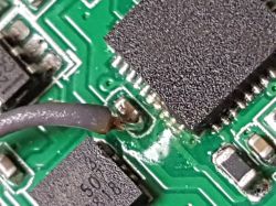
Since the USB-RS232 converter works with TTL levels, it became necessary to use a level converter in the form of a resistor divider on the Tx line and a transistor shifting the levels from 3.3 to 5V on the Rx line of the converter.
For now, there is a wire shop, maybe I will make another more solid platform with the DA14585 board.
First program on DA14535
The SDK provided by Renesas includes example projects. They are in the location
DA145xx_SDK/6.0.18.1182.1/projects/
At the very beginning, it is worth loading and compiling one of the projects, without your own modifications, to check the operation of the environment.
I chose the project target_apps/peripheral_examples/blinky.
It has a structure:
Code: Bash
The structure is clear - project files in a given IDE and program sources have been separated.
Looking at other projects, it's easy to conclude that Renesas prefers Keil over its SmartSnippets™ Studio for this SoC.
You can see what the project looks like in another IDE by looking, for example, at the directory: projects/target_apps/ble_examples/prox_reporter/
Code: Bash
For me, the projects compiled right away, so I started creating my project based on blinky.
I used the previously mentioned UM-B-057 guide, which describes, among others, procedure for creating a project on the basis of an existing one.
First, I changed the name of the project and its location relative to the SDK, changing all paths in the *.uvprojx file to the correct ones. I left the *.c and *.h files so that the project structure looks like this:
Code: Bash
The program writes text to the UART, which contains consecutive prime numbers in hex format. Numbers are calculated in a very suboptimal way using modulo division.
The duration of the loop depends on the currently counted prime number, the larger the longer it lasts.
[syntax=c]int isPrimeNumber(int n) {
int i;
for(i = 2; i
Cool? Ranking DIY


