Elektroda.com
Elektroda.com
X

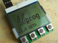
uProg - small, fast, portable AVR programmer with SD

manekinen 144241 364
This content has been translated flag-pl » flag-en View the original version here.
  • uProg - small, fast, portable AVR programmer with SD
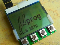
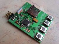
    The only such portable AVR programmer. It will help wherever you need to update the software, and the target chip is in a hard-to-reach place and we do not have the ability (or the desire) to drag a laptop and a lot of wires with us. Easy to use, low cost, super small, super fast, supports SD cards ...

    Characteristics:
    -supermal - dimensions only 44 x 39 x 5.5 mm
    -superfast - write to 12.5kB / s , read to 14.5kB / s
    - uses a cheap data carrier - ubiquitous SD / MMC cards
    -supports the file system FAT16 and FAT32
    -read, save, verify the memory flash and eeprom
    -read, write, verify fusebits and lockbits
    -writing and reading to files BIN , HEX and TXT
    -can set factory fusebit values, delete memories
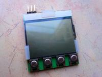
    - cheap, easily accessible graphic display - LPH7779
    -displays fun animations after each operation
    -standard Atmel programming connector 6-PIN ISP
    -has auto-update feature of its own software
    -very simple operation, 4-button navigation
    - user settings menu
    -automatic selection of programming speed (up to 4MHz )
    -work at 3V, system programming from 3V to 5V

    Service:
    The programmer is turned on by holding down the button LE (left). The first thing we see is the welcome screen and version information - this information disappears after a while and we can now navigate in the menu. With buttons UP (top) and DN (down) select the required option with the button RI (right) confirm the operation / enter the menu option, and press the button LE (left) we cancel the operation, go back to the menu, which looks like this:

    Flash: > Write> Read> Verify
    Eeprom: > Write> Read> Verify
    Fusebits: > Write> Read> Verify> Default
    Lockbits: > Write> Read> Verify> Chip erase
    Settings: > Auto Verify> Auto Erase> Show Anims> Progr bar> Files type

    Function description:
    Write - saves the contents of the file from the card to the selected memory. Select a file from the list. In case of fusebits or lockbits, save setting bytes (from txt file). The length of the file is the length that the programmer will write to memory, the rest of the memory will not be saved.
    Read - reads the contents of the selected memory and writes to a file on the card. The file is created automatically in the appropriate folder. The name format is "x.yyy", where x is the sequence number of the file and yyy is the BIN or HEX extension. For example "4.bin" or "22.hex" - the name is displayed and it is good to write it down somewhere. All available memory will be read, no matter how much data is in it. In case of fusebits or lockbits, writes the setting bytes to the txt file to the file.
    Verify - compares the contents of the selected memory with the contents of the indicated file, the result of the operation is "PASS" or "FAIL at x", where x is the number of the first cell in which the inconsistency occurred. For fusebits or lockbits, compares setting bytes.
    Default - resets all fusebits to factory values.
    Chip erase - the internal "chip erase" command clears the entire memory of the chip and resets the lockbit protection.

    Description of the settings:
    Auto verify - enables automatic memory verification (like the "verify" option), but it does it automatically after each save. Settings: ON or OFF. It applies only to operations on flash and eeprom memory, fusebits and lockbits bytes are read immediately after writing.
    Auto erase - automatically executes the "chip erase" command before each write to the flash memory. Settings: ON or OFF. Only valid for flash memory, which must be cleaned before writing. The exception is when we know that the memory is cleared, and at the end we have, for example, a bootloader loaded. Disabling this option will overwrite the data without wiping the content, which in turn will keep our bootloader or other data.
    Show anims - displays short animations after each operation depending on whether it was successful or not. Settings: ON or OFF. The animations can be interrupted at any time by pressing the button LE . These are funny animations and add a specific character to the programmer, an experienced internet user will surely recognize them :) Animations are BMP files from a given folder that play one after the other - so you can replace them with your own! File format: Bitmap (* .BMP), 84x48 pixels, monochrome (2bit). The order of playback is not alphabetical, files are played in the order in which they were copied to the card.
    Bar program - progress bar for write, verify and read flash and eeprom operations. Settings: ON or OFF. The progress bar slightly slows down the process, see "speed tests".
    Files type - choosing the type of files we want to work with. Settings: BIN or HEX. It applies to operations on flash and eeprom memories, depending on the selection on the list, only files of a given type will be displayed. When reading to a file, an appropriate file will also be created (in the case of HEX files, the checksum will also be counted).

    Memory card, files:
    Files should be placed on the card in appropriate folders, ie files for flash memory in "flash" folder, eeprom in "eeprom", fusebits in "fuseb" and lockbits in "lockb". The "system" folder contains other files needed for the programmer to work, m.in. uProcessor database, a file that stores settings or BMP images. The CONTENTS of the "SD-FILES" folder from the attachment should be copied onto the memory card.

    While in the case of BIN flash and eeprom files there is no doubt, because they are files generated by compilers, the structure of fusebits and lockbits should be described. These are ordinary text files, into which we enter values in hexadecimal form:

    The fusebit file should contain data for: fuse low, fuse high, fuse extended - in HEX format. For example, the contents of the fusebit file for Attiny45 should look like this: 62DFFF. The file may be longer, it may have additional comments, but only the first three bytes (6 characters) will be taken into account. If the processor has two or only one byte of fusebits, then of course only that number of bytes will be used.

    The structure of the lockbits file is similar to that of the fusebits file. The only difference is that only one byte will be used here, but remember that unused bits must always be 1. So if we want to turn on LB0 and LB1 bits, use the "FC" value (11111100). In the case of fusebits, the same rule applies, although even if we act differently and try to include non-existent bits (write 0 in them), we will get an error during verification, because these bits will be 1.

    When reading fusebits and lockbits to a file, the programmer will create text files according to the above-described scheme.

    By selecting the appropriate memory in the menu and then saving or verifying, a list of available BIN / HEX or TXT files from the appropriate directory will be displayed. The files are not sorted alphabetically or otherwise, they appear in the order they were copied and / or created. You can place as many files as you want, all of them will appear in the list. Select a file with buttons UP and DN , confirm with the button RI , canceling with the LE button. There are 6 names on the screen at a time, the next file card is revealed after pressing DN when the last file on the card is indicated. File tabs can only be switched forward (down), after reaching the end, the first tab will be displayed.

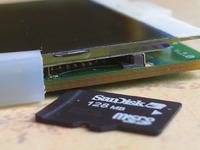
    The programmer supports cards MMC and SD . The cards I have tested are: 128MB, 512MB, 1GB, 2x2GB. The file names are optional, but on the display they will appear in DOS 8.3 format (8 characters + extension). Longer files will be separated by a tilde ( ' ), and if their names in the first 8 characters differ, the files will be marked with a sequence number. Diacritical marks and other inventions will also not be displayed - so I advise you to name the files legibly so that there is no problem with identifying them later.

    Planned: SDHC card support.

    Power, voltage:
    The system is designed to work with battery power, but nothing prevents you from using the appropriate power supply.
    Nominal working voltage: 3.3V
    Maximum working voltage: 3.6V
    Minimum operating voltage: 2.7V *
    Current consumption during startup: up to 100mA *
    Current consumption during the programming process: approx. 10mA *
    Current consumption in the menu: 5mA
    Stand-by current consumption: 0.10uA

    * depending on SD card inserted

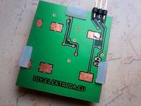
    On the bottom of the board, there is a place for soldering two CR2032 battery sockets - the operating voltage will be 3V, and the current efficiency of such batteries will usually not allow power to be connected to the programmed circuit - a voltage drop will likely make a mess on the programmed circuit or on the memory card. Instead of soldering the sockets, another battery with higher capacity can be used (it can be, for example, a battery from a mobile phone), but the maximum operating voltage must not be exceeded.

    The entire programmer works with the voltage it will receive from the battery, because it has no stabilizer. The programming process also takes place at this level (high state). The target (programmed) circuit can be programmed with voltages from 3V to 5V, when the programmer works at 3V. On the one hand, on the input line MI-SO there is a protection in the form of a resistor and a 3V3 zener diode, which will protect the programmer input against too high voltage, and on the other hand, the system powered by 5V will correctly recognize the high state at 3V on the MO-SI and SCK lines (see note: electrical characteristics> dc characteristics> V IH = 0.6 VCC which means nothing but 0.6 * 5V = 3V - this is the guaranteed value).

    The programmer does not have a mechanical switch, switching it on and off is done by holding down the button LE . After switching off, the programmer cuts off the power supply to the display and the memory card, and goes into deep sleep mode by taking (typically) 0.1uA from the battery.

    AND SP:
    Connectors:
    uProg - small, fast, portable AVR programmer with SD
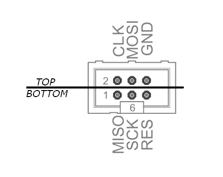
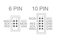
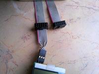
    The programming pin is 6pin male as standard ISP ATMEL . The location of the pins is shown in the drawing, the plug is indented on the bottom side of the board. You can easily make a ribbon with a 10pin female socket as standard ISP KANDA or a universal ribbon with a combination of 10PIN and 6PIN sockets. Zones after programming SCK , MOSI , MISO and RESET they become transparent to the target layout.

    Automatic selection of programming speed:
    At each initiation of programming with the target system, the programmer automatically selects the programming speed (clock line speed SCK). There are 7 steps of adjustment: 4MHz, 2MHz, 1MHz, 500KHz, 250KHz, 125KHz, 62,500KHz. Theoretically, it will be 1/4 of the target system operating frequency, but not always. The programmer starts at the highest speed every time and performs the signature read test 10 times - if any error occurs, the speed will be reduced and the test repeated until it goes down to the lowest speed. If the lowest speed fails, the programmer will return a message stating that the system is not responding. In the case of a very long splicing tape, the programmer may use a lower speed if errors occur - a short test may not reveal communication errors that may not be released until the memory is written. I recommend using a tape no longer than 20 cm. The given SCK values refer to the timing of the programmer chip at 8MHz.

    Auxiliary clock signal
    Since the programmer is battery powered, I resigned from the usual function of the VCC pin (pin 5 of the 6 ISP socket) and there is no possibility of supplying power to the target circuit on this pin. Instead, this pin has an auxiliary 8MHz clock signal that can be used if the target has some strange / external clock source set. This signal is connected through a 1K resistor, so it is not necessary to modify the connecting strip if there is voltage on this line from the target circuit.

    Software update:
    If a new version of the software is released, there are two ways to update it:
    AND SP: Connect your programmer to the ISP-6 connector and shorten the pins marked as "SLF-PRG" - this will make this connector a software update connector (as in USBasp).
    BootLoader: The device has a built-in bootloader, thanks to which the firmware can be updated very easily! Copy the firmware update BIN file to the root directory of the card and name it "000.bin". If nothing appeared on the display after turning the system on - that's good! The file with the new firmware has been correctly recognized, now just press the button RI to confirm that you want to update. The device will update its firmware by itself, it will take a few seconds, and then start up - the welcome screen will show the new version of the program - that's it! Now it is enough to delete the previously uploaded file from the card so that the device does not start up in the update mode. In the update mode, some cards may not be supported - so if after uploading the "000.bin" file the device started normally - this is one of these cards.

    Remarks:
    Fusebits: Ext: 07, high :D 0, low: A2
    (internal 8MHz oscillator without / 8 split, CLKO output on, 2.7V brown-out detection, reset vector to bootloader address, 4kB bootloader memory, EESAVE on)

    The internal Atmegi328P oscillator can be calibrated over a very wide range. The factory calibrated clock up to 8MHz can be "calibrated" from 50% to even 200%, that is from 4MHz to even 16MHz. Changing bit4 in the "config.ini" file to "1" will select the maximum frequency - it will significantly speed up the programming, but the manufacturer does not guarantee stable operation in such conditions (supply voltage vs frequency). Initially, this setting is turned off.

    The display I used is original - it has the PCD8544 driver, 84x48 organization, a standard set of instructions for it, and it can accept data with a maximum clock of 4MHz - and it works at this speed. If your display shows stupid things or nothing, there are two possibilities:
    and) it has a driver other than PCD8544 - in the "config.ini" file set bit6 to "1" - the display will be treated differently, although it does not guarantee correct operation.
    b) it cannot work at 4MHz - in the "config.ini" file, set bit5 to "1" - the display will work at 2MHz, this speed should not cause problems for him.

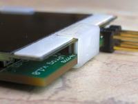
    The display needs a capacitor for the built-in voltage converter (C2, C3), the nominal value is 1 uF. For me, it works successfully with a capacitance of 200nF. If you have problems with contrast, increase this capacity - in place of C2 and C3 you can side-solder several SMD capacitors. If the display has solder pads, you can connect it with wires - if it has contact pads, use the contact eraser that was in the phone and attach the display well. Despite the fact that my display has solder pads, I just used a contact eraser. The handles are made of a fragment of the housing "E + J connectors" . It can be any fragment of anything with an internal dimension of 5.2mm - just such a connector was at hand :)

    The memory card, depending on which one is hit, consumes a "very large" current at start-up - around 100mA. Very large, i.e. for the possibilities of a coin cell battery. The C4 capacitor helps to maintain the voltage during card initialization, it is good to have the highest possible capacity, but also without exaggeration - the capacitor is charged by three pins of the processor, they cannot be overloaded. For me, 10uF is enough to start all the cards that I tested, but as the battery is discharged, problems may appear.

    The programmer operates only in its own folders and will not move through the rest of the folders / files on the card. CAUTION - however, it should be borne in mind that due to some error the file structure may be damaged and the data on the card may be irretrievably lost or it will be difficult to recover it! This can happen when removing / inserting the card while the machine is running or power is cut off while reading / writing. It may also happen (very rarely) that the programmer will hang when trying to open a list of files in a folder. The solution to the problem is to delete the most recently created file in this folder by the programmer.

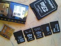
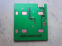
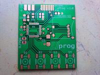
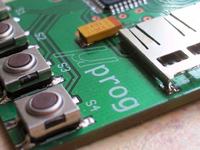
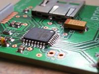
    39mm x 44mm x 5.5mm PCB, double-sided. The pads of the guides are located in easily accessible places (not under the housings), so the plate can be successfully made at home. The micro SD card slot I used is quite popular MSDE208, the footprint comes hence that is from socket 500873-0806 - as you can see, it is not a problem to find several compatible sockets, just look for one that has its pads "underneath" and compare it with the datasheet - it should match.

    Speed Tests:
    Programming speed test made with Atmega644A (as target) working at 25MHz, 4MHz SCK speed, flash memory, 64kB data size, 16MHz programmer chip timing:

    BIN file, disabled progress bar:
    Save from file: 5,1s.
    Read to file: 4,4s.

    BIN file, enabled progress bar:
    Save from file: 5,1s.
    Read to file: 5,0s.

    HEX file, disabled progress bar
    Record from file: 12.5s.
    Read to file: 11.6s.

    HEX file, enabled progress bar
    Record from file: 12.5s.
    Read to file: 12.2s.

    As you can see - the best results can be obtained with BIN files, because its size is the data length and there are no quirks. Reading from a HEX file requires previously to "fly" the entire file and count all bytes contained in it, and when writing to such a file, the checksums of each string are counted - so it takes a while.
    The progress bar hardly slows down the process when the target layout is page-programmed (as in the test above). In the case of programming bytes or reading (which is always implemented byte by byte), the enabled progress bar will significantly slow down the operation.

    List of supported chips:
    Systems tested in practice: tiny13, tiny45, tiny2313, mega8, mega88, mega16, mega32, mega328, mega644
    Not all chips are fully supported yet, see file "chip.db". Incomplete entries mean that only fusebits and lockbits operations will work.
    The list of tested chips will be updated on the project home page.

    1kB:
    AT90s1200, Attiny12, Attiny13 / A, Attiny15
    2kB:
    Attiny2313 / A, Attiny24 / A, Attiny26, Attiny261 / A, Attiny28, AT90s2333, Attiny22, Attiny25, AT90s2313, AT90s2323, AT90s2343
    4kB:
    Atmega48 / A, Atmega48P / PA, Attiny461 / A, Attiny43U, Attiny4313, Attiny44 / A, Attiny48, AT90s4433, AT90s4414, AT90s4434, Attiny45
    8kB:
    Atmega8515, Atmega8535, Atmega8 / A, Atmega88 / A, Atmega88P / PA, AT90pwm1, AT90pwm2, AT90pwm2B, AT90pwm3, AT90pwm3B, AT90pwm81, AT90usb82, Attiny84, Attiny85, Attiny8685, Attiny86901 / Attiny1588, Attiny86901 / Attiny
    16kB:
    Atmega16 / A, Atmega16U2, Atmega16U4, Atmega16M1, Atmega161, Atmega162, Atmega163, Atmega164A, Atmega164P / PA, Atmega165A / P / PA, Atmega168 / A, Atmega168P / PA, Atmega169m216, ATmega168P / PA, Atmega169m216, Atmega169167A
    32kB:
    Atmega32 / A, Atmega32C1, Atmega323 / A, Atmega32U2, Atmega32U4, Atmega32U6, Atmega32M1, Atmega324A, Atmega324P, Atmega324PA, Atmega325, Atmega3250, Atmega325A / PA8, Atmega3250A32, Atmega3250A32, Atmega3250A32 / PA8, Atmega3250A32 / PA8, Atmega3250A32 / PA8, Atmega3250 PA, AT90can32
    64kB:
    Atmega64 / A, Atmega64C1, Atmega64M1, Atmega649, Atmega6490, Atmega649A / P, Atmega6490A / P, Atmega640, Atmega644 / A, Atmega644P / PA, Atmega645, Atmega645A / P, Atmega6490usb64, ATmega649064, ATmega649064764
    128kB:
    Atmega103, Atmega128 / A, Atmega1280, Atmega1281, Atmega1284, Atmega1284P, AT90usb1286, AT90usb1287, AT90can128
    256kB:
    Atmega2560, Atmega2561

    Project home page: uProg - small, fast, portable AVR programmer with SD
    uProg - small, fast, portable AVR programmer with SD uProg - small, fast, portable AVR programmer with SD uProg - small, fast, portable AVR programmer with SD
    uProg - small, fast, portable AVR programmer with SD uProg - small, fast, portable AVR programmer with SD uProg - small, fast, portable AVR programmer with SD
    uProg - small, fast, portable AVR programmer with SD uProg - small, fast, portable AVR programmer with SD uProg - small, fast, portable AVR programmer with SD
    uProg - small, fast, portable AVR programmer with SD uProg - small, fast, portable AVR programmer with SD uProg - small, fast, portable AVR programmer with SD
    uProg - small, fast, portable AVR programmer with SD uProg - small, fast, portable AVR programmer with SD uProg - small, fast, portable AVR programmer with SD


    In Attachment:
    Eagle 5.10 files: PCB, SCH; alternative PDF; Batch HEX and BIN; support files.
    PCB ver. 1.0
    Program ver.1.0 - BETA version.

    -stable beta version
    -writing / reading / verification over 128kB (extended memory chips) has not been tested, but is implemented
    - write / read / verify HEX files only guaranteed up to 64kB - also not tested
    -programmer fully tested with: tiny13, tiny45, tiny2313, mega8, mega88, mega16, mega32, mega328, mega644

    Before uploading a flash, please read the THIS LINK

    //update

    Update # 2 is here HERE

    PCBs and displays are available HERE
    Attachments:

    Cool? Ranking DIY
    About Author
    manekinen
    Level 29  
    Offline 
    manekinen wrote 1629 posts with rating 2330, helped 76 times. Live in city Kętrzyn. Been with us since 2006 year.
  • #2
    cooltygrysek
    Conditionally unlocked
    Briefly WOW !! Description and perfect workmanship, there is nothing to ask. Something like this will be useful to everyone, so you will probably order a lot of tiles :-) I have one question, what are the costs of your programmer ??
  • #3
    maniak0790
    Level 23  
    LCD probably from Nokia 3310. How did you solder the memory card slot to the HA station? You did not think about your own production and sale of such a programmer before sharing the files. Make another housing.
  • #4
    ZapleT
    Level 15  
    Shocking! My sneakers fell off my feet :D Before such DIY, there should be warnings so that a person would have time to sit down.
    manekinen wrote:
    you can use another battery with higher capacity (it can be, for example, a battery from a mobile phone)

    Will the device work properly with lithium polymer batteries? Have you had the opportunity to check it?
  • #5
    stepawel
    Level 15  
    Great device. I used to think about something like that, but unfortunately it only ended there.
    I think that the programmer could still communicate via USB with the computer.
    Of course, I'm giving it a nice one, although it's definitely too low a grade :)
  • #6
    Belialek
    Level 22  
    Project of the year for me. I sincerely congratulate the idea, knowledge and implementation of the device - as well as the documentation itself. Traditionally, all the materials needed to recreate the project at home are published :) And that's what DIY should look like!
  • #7
    perszeron
    Level 21  
    Nothing more nothing less design for 6+ I am impressed with the idea and implementation,
    many people copying the project will definitely use 3.7V rechargeable batteries with mp3 etc. maybe to add a battery test, my inborn laziness would like to ask how much (roughly) the tiles would cost, I know that it depends on the quantity you order, but the forks + -
    Regards ;-)
  • #8
    manekinen
    Level 29  
    lukas12 wrote:
    What have you learned to do something like that

    Hmm, I don't quite understand the question :) I used a ready and proven SD card library, on the forum I found a program to operate the display (and I modified it a lot, it was resource-consuming), the ISP protocol and the necessary data are in the AVRk notes - all this is needed to be put together by writing the program so that the process itself programming (rewriting a byte from one hardware SPI to another) was not slowed down by any unnecessary instructions.

    norbis15 wrote:
    I am shocked by the perfection of workmanship. I am adding to the question of Lukas12. What is this display?

    Display, LPH7779 - that is from the Nokia 3310 phone.
    cooltygrysek wrote:
    I have one question, what are the costs of your programmer?

    Very low, I only bought a card slot for PLN 3, Atmega328P-20AU for probably PLN 14, and I made 5 prototype boards for PLN 69 (i.e. one 13.8). The rest of the parts are small items that everyone probably has. The display and the eraser to connect it come from the phone. So as you can see, it comes out about PLN 30 :)

    maniak0790 wrote:
    How did you solder the memory card slot to the HA station?

    No, a soldering iron with a very thin tip. I insert the SD card from the side, and through the holes you can clearly see what is happening. Only then I noticed that this plate from the socket can be easily removed (latches) and the next ones were soldered, disassembled and then the plate clicked into place. You just have to be careful not to lose the mechanism that ejects the card.

    maniak0790 wrote:
    You didn't think about your own production and sale of such a programmer before sharing the files.

    Of course I thought. But I give it completely for free ;)

    ZapleT wrote:
    Before such DIY, there should be warnings so that a person would have time to sit down

    I hope that my friend did not hurt himself, please take a sitting position in the future ;)

    ZapleT wrote:
    Will the device work properly with lithium polymer batteries? Have you had a chance to check it out?

    I haven't checked, but I don't see any reasons why something won't work - since it works on two coin-cell batteries. It is important not to exceed the permissible voltage. Although during the first tests on a new PCB I accidentally gave 5V for several seconds - everything survived.

    stepawel wrote:
    I think that the programmer could still communicate via USB with the computer.

    Well, I was already offered it, but I still don't understand why? The card itself provides great convenience. Hm?

    stepawel wrote:
    Of course, I'm giving it a nice one, although it's definitely too low a grade

    Thank you, thank you.
    perszeron wrote:
    maybe would add a battery test

    No problem, the board is ready so that the system can measure its own supply voltage. And if I ordered the boards, they would not be prototypes anymore, and with more, they should be cheaper. I need to find out.

    cooltygrysek wrote:
    Description and perfect workmanship, there is nothing to ask

    I noticed that topics that contain careful and comprehensive descriptions have very few posts, and those without descriptions go on and on because everyone is asking about something :)

    Regards!
  • #9
    piotrva
    VIP Meritorious for electroda.pl
    The project was known to me before and once again I bow to my friend mannequin for another polished and useful project. Great + for the lifetime.
    ---
    This comes to my mind, because this project is really DIY and it contrasts strongly with the level of complexity and performance with the recently presented 4 power supplies on ready-made products, maybe the administration would do the "DIY Power Supplies" section? :D
  • #10
    Karol966
    Level 31  
    Tomekddd wrote:
    Brilliant, if you were to order tiles and displays, I would ask for information, e.g. on PW or meil.


    To write it too little:
    Quote:
    If you are interested in the tile - do not ask on the forum or at PW, but take the poll on the home page - thanks to this I will know how many people are willing and I will be able to order tiles. Then I will post the relevant information.


    To the author. Everything in Bascom? You probably don't plan to change to C in the future? You can write in which company you made the tiles. This is the age-old problem with this choice of company. PS. Maybe you will write on your website with the probe the approximate cost of the plate with a larger order. Another thing is the power supply - is the battery really necessary? Power could be drawn from the target circuit. What is the current consumption of this system?
  • #11
    Tomekddd
    Level 23  
    Quote:
    Power, voltage:
    The system is designed to work with battery power, but nothing prevents you from using the appropriate power supply.
    Nominal working voltage: 3.3V
    Maximum working voltage: 3.6V
    Minimum operating voltage: 2.7V *
    Current consumption during startup: up to 100mA *
    Current consumption during the programming process: approx. 10mA *
    Current consumption in the menu: 5mA
    Stand-by current consumption: 0.10uA

    * depending on SD card inserted


    I suspect that it would only be possible to deal with the voltage levels, here is 3.6V and many systems use 5V
  • #12
    Karol966
    Level 31  
    2 diodes are enough, e.g. 1N4001 ;) just 5 will remain 3.6V. If this start-up was not so energy-consuming, the battery would probably be enough.
  • #13
    syntetyczn dran
    Level 12  
    Somehow suspiciously cheap, these tiles came out to my colleague. I join the question, what company is it? :) Because at this price, it somehow ceases to pay off to make it yourself. Because it is a waste of time and nerves :P
  • #14
    poorchava
    Level 18  
    The project is very interesting and useful. For example, it beats a similar programmer-to-go function in Microchp tools. The degree of reflection and "spatial" design of the whole thing is admirable.

    I would honestly try to squeeze the FT232 + USB mini / micro B there, or at least max2323. The reason is simple. Many computers do not have a card slot, and everyone has USB.

    Of course, instead of FT, you could use the avrusb (or something like this.anyway - a soft usb on AVR that is, for example, in usbasp)

    Pytanko: where did your friend order tiles?
  • #15
    eurotips
    Level 39  
    Such a hardware programmer has many advantages, but will also cause several problems that do not occur in typical programmers operating via the USB port, e.g. own power supply and its monitoring, i.e. either a rechargeable battery or a cable, this time only used for power supply. Also, the upgrade options are more limited, and Atmel often adds something to the collection.
    Maybe a useful thing in a production plant, because to have 10 programming stations you do not need 10 licenses for Win and Progd, but for a hobbyist it does not make sense such autonomous programming.
    For innovation, you have to admit to your colleague 120/100,
    which you can see from the interest,
    a gem among DIY on the Electrode.
  • #16
    lukas12
    Level 17  
    BASCOMA you have learned individually or through school :?:
  • #17
    leonow32
    Level 30  
    poorchava wrote:
    I would honestly try to squeeze the FT232 + usb miniB / microB there, or at least max2323. The reason is simple. Many computers do not have a card slot, and everyone has USB.

    But what for? This is the idea behind this device to work without a computer. An SD card is a necessity, because somewhere else for reasonable money to keep programs - for example AT24C1024 would be enough for one ATmega128 batch, and it costs PLN 20. The SD card with the connector will be cheaper, and you can buy a computer reader for PLN 1, so it's not a problem.
  • #18
    krzycho123
    Level 31  
    I am very impressed, the layout is incredibly thoughtful and useful. The tiny device can hide anywhere.

    Perfect for the field, it's strange that no one has started to sell it commercially before :D
  • #19
    drzasiek
    CNC specialists
    lukas12 wrote:
    BASCOMA you have learned individually or through school :?:

    And who is studying at the Bascoma school at AVR now? :) Bascom is programmed by those who used to want to program but did not know any language yet, and for self-taught people it is probably the easiest one.
    As for the design, it's a super simple device in terms of hardware (just look at the board), and I think that if you read a little bit, it's not too complicated in terms of software, and it inspires great respect for the designer !!! But why? Because it is useful, because it is not a 100th copy of a power supply, linefollower or RGB lamp, but it is a well-thought-out and designed project from the very beginning. Cool! That's what DIY is all about :)
    It is a pity that there are no more competitions in the DIY department :( It is worth rewarding such projects.
  • #20
    narasta
    Level 21  
    lukas12 wrote:
    BASCOMA you have learned individually or through school :?:

    They teach Bascom even during studies (whoever wants to choose projects can write in C), but they certainly do not teach such advanced things as SD or ISP libraries ...
    What at school ends with lighting up the LEDs or writing Hello World on the LCD screen.

    I am also curious where did you intend the PCB?

    I am impressed that you managed to put together a code from several different larger parts, and that in BASCOM. You like to make your life difficult. So you are ambitious :P

    You've put everything together elegantly, just the casing and the guitar :)

    Make the next SW version the ability to manually enter fusbits - 4 buttons are enough for this purpose.
  • #21
    shadow0013
    Level 34  
    Great respect for the idea and implementation of the project and software in Bascom (I would ask for sources for teaching purposes).
    For lazy colleagues, the cost of implementing the project:
    - Nokia 10-30 PLN display (depending on the source and whether a phone is attached to it),
    - processor from PLN 10-12-20 (depending on the source of purchase)
    - microSD slot 0-3-10 PLN. (depending on the version, source and whether a telephone is attached to the socket),
    - the price of the plate depends on the author of the topic (poll on his website - depending on the number of users),
    - the rest are trifles - a few zlotys
    The prices come from Allegro and several online stores - of course there is a shipping cost (s) of 7-18 PLN. For the impatient - sometimes it is worth buying parts in local stores (more expensive but faster - you go and have it - sometimes).
  • #22
    manekinen
    Level 29  
    piotrva wrote:
    The project was known to me before and once again I bow to my colleague for another refined and useful project. Great + for the lifetime.

    Thanks, remember that when you have some free time, let me know and he will recommend a CD ;)

    Karol966 wrote:
    To the author. Everything in Bascom? You probably don't plan to change to C in the future?

    Yes, bascom. There are no plans to change to C because I have no time to learn it at all, and I made friends with bascom (I know what it stings some people's eyes). And please, end the discussions about C / Bascom with this ;)

    syntetyczn dran wrote:
    Somehow suspiciously cheap, these tiles came out to my colleague. I join the question of what company is this? Because at this price, it somehow ceases to pay off to make it yourself. Because it is a waste of time and nerves

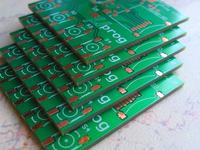
    Tiles made in satland prototype - PLN 68.08 with shipping - 4 tiles. They sent 5. I would not like to do an advertisement, but the tiles are perfectly made (the holes are slightly shifted), and I could not get enough of the edge quality for a week, it is so perfect that the tiles can be placed vertically :)

    poorchava wrote:
    I would honestly try to squeeze the FT232 + usb miniB / microB there, or at least max2323. The reason is simple. Many computers do not have a card slot, and everyone has USB.

    Of course, instead of FT, you could use this avrusb (or something like that.anyway - soft usb on AVR that is, for example, in usbasp)

    The card reader literally costs a few zlotys. On USB. A soft USB for bascom also exists, but it will be rather a snail. I still don't see any reason for pushing the USB in there. Hm? I don't know what happened to you, it's probably a mania, because nowadays, there is a usb in every single device, even the systems flashing with a diode have a usb to click the button and "flash via usb" ;)

    eurotips wrote:
    Maybe a useful thing in a production plant, because to have 10 programming stations you do not need 10 licenses for Win and Progd, but for a hobbyist it does not make sense such autonomous programming.

    But it is not intended to be used on some programming stations in the production of some devices. Imagine that you have a meteorological system installed somewhere on a pole / tree / roof and you want to update the program in it. Are you going in there with your laptop? ;)

    leonow32 wrote:
    But what for? This is the idea behind this device to work without a computer. An SD card is a must, because somewhere else for reasonable money to keep programs - for example AT24C1024 would be enough for one ATmega128 batch, and it costs PLN 20. The SD card with the connector will be cheaper, and you can buy a computer reader for PLN 1, so it's not a problem.

    Thanks! This is what it is all about.

    krzycho123 wrote:
    I am very impressed, the layout is incredibly thoughtful and useful. The tiny device can hide anywhere.

    If you are going to order a group of PCBs, let me know, a lot of people will be interested.
    I would definitely take a few pieces, if you don't, let me know where you order such cheap prototypes

    After all, I will, please take part in the tile survey.
    drzasiek wrote:
    As for the design, it's a super simple device in terms of hardware (just look at the board), and I think that if you read a little bit, it's not too complicated in terms of software, and it inspires great respect for the designer !!! But why? Because it is useful, because it is not a 100th copy of a power supply, linefollower or RGB lamp, but it is a well-thought-out and designed project from the very beginning. Cool! That's what DIY is all about
    It is a pity that there are no longer competitions in the DIY department. It is worth rewarding such projects.

    You can always vote and I will get some gadgets? :)
    There are practically no differences in the software / hardware SPI, but the first one is several times slower and you have to create it yourself. Well, unless it was the ISP protocol. This is the most ordinary in the SPI world, you send the data given in the datasheet table and that's it - no philosophy. Well, it's worse in practice :)

    narasta wrote:
    You've put everything together elegantly, just the casing and the guitar

    Case? Hmm, the screen and the board form the housing. The screen can be caught on a double-sided tape so that it does not move to the sides - a minimal shift means that the contact eraser misses the pins and you can no longer see anything. You cannot carry it in your pocket because of the screen that will break quickly, but if someone needs more strength, of course it can be incorporated into a housing.

    narasta wrote:
    I am impressed that you managed to put together a code from several different larger batches and still in BASCOM

    It was the easiest thing to do! ;)

    narasta wrote:
    Make the next SW version the ability to manually enter fusbits - 4 buttons are enough for this purpose.

    A good idea, and maybe you will develop what it would look like? Single bit switching? Or maybe increasing / decreasing the hex value?

    maniakhv wrote:
    Is it possible to change the display to LCD ??

    Probably this is about the HD44780. I was wondering about the through-hole version that would use such a display. It would be a more accessible version for everyone, because not everyone can put together such trinkets.

    Added after 2 [minutes]:

    shadow0013 wrote:
    (I would ask for resources for teaching purposes)

    I do not provide the sources. You can probably guess the reasons? Alternatively, I can show some fragments if someone knows what he is asking :)
  • #23
    qscgu
    Level 34  
    drzasiek wrote:
    narasta wrote:
    They teach Bascom even in college

    What studies do they teach BASCOMA at?

    I'm also very curious because we had AVR and the hosts didn't even mention that something like bascom even exists.

    We did everything in C and even in Assembler. (Silesian University of Technology - Gliwice)
  • #24
    Sebastian.R
    Level 20  
    I am MEGA impressed. I have USBasp, recently USBtiny, but your project beats them :D . Well, yes, let's assume that we are dealing with a computer protected by an administrator password. We will not run the above-mentioned programmers, because it will scream for drivers, and if we do not have access to the system to install it, it is all hell. Your project solves the matter. We put a hex or bin file and epp and lu on the card! we program without a computer.
    If I could ask for something, is there a version of this design with the LS020 display - from the old Siemens CX65? Color display. It would look even more "fabulous". Regards.
  • #25
    lukas1121
    Level 18  
    growing up with this Hello World I agree 100% :D I know the hard way.
    And the showpiece project would be worth putting it up in some competition, so that it would not have :D
    Or maybe the administration would think about rewarding users with such spectacular works ?? After all, such a construction is, so to speak, a dying species :( a job well done must be promoted.
  • #26
    Tomasz.W
    Level 35  
    lukas1121 wrote:
    .... And the showpiece project would be worth putting it up in some competition, so it wouldn't have had a bigger competition :D ....
    You say that he would not have competition.
    As I know life, a board with valgus holes described as would win anyway COLUMN :cry:
  • #27
    manekinen
    Level 29  
    Sebastian.R wrote:
    If I could ask for something, is there a version of this design with the LS020 display - from the old Siemens CX65? Color display. It would look even more "fabulous". Regards.

    No, it does not exist, and is unlikely to arise. Time-consuming, lack of memory space for such things, higher power consumption, and the excess of form over content.

    Gentlemen, thanks for the kind words, because this is probably the best motivation for further work on the layout :)

    I will add photos of tiles in high resolution https://www.elektroda.pl/rtvforum/viewtopic.php?p=9600875#9600875

    You have already broken a lot of votes in the poll, half of you would prefer the PCB + LCD set. I will also look around for displays, and on Monday I think I will order the first batch of tiles.
  • #28
    leonow32
    Level 30  
    manekinen wrote:
    You have already broken a lot of votes in the poll, half of you would prefer the PCB + LCD set. I will also look around for displays, and on Monday I think I will order the first batch of tiles.

    But before you order it, better make records and prepayments. Unfortunately, I already know what such "social actions" can end with - when it comes to paying, everyone will change their mind, and you will have a lot of tiles with which you will not know what to do.
  • #29
    perszeron
    Level 21  
    I also have a question for the author where he will give info that the tiles are available for purchase, I am interested in 2 pieces myself, I will also add that come connecting this module to the computer and programming directly via the computer would be slow to add universality to the project, it is worth considering such an option, all the more if you could use the same link computer> module to select the resources of the card to modify the files on the card, e.g. in the menu, add a disk tab and the card would be seen as a normal disk ... for a source batch I do not even dare to ask :-)
  • #30
    manekinen
    Level 29  
    krzysiekdg wrote:
    I have a question, does it have to be the Atmega328P-20AU or it can be atmega32?
    I am asking because I have only uP smd, ordinary 32 pin, and even in the photos there is probably atmega32 - 40 pin.

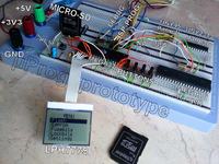
    One of the photos shows the Atmega32-16PU because it was just a prototype. You have Atmega328P-20AU in the diagram and you need to use it. In truth, there are no big differences (Atmega32 has only one hardware SPI) but the code will not work on Atmega32, they are completely different chips and you cannot simply use them interchangeably.
    perszeron wrote:
    I would like to add that it is possible to connect this module to the computer and programming directly via the computer would be slow, it would add universality to the project, it is worth considering such an option

    There will be no USB, there is no such option. Neither the board is prepared for this, nor is there any memory space for such things. I would have to crash the bootloader to get 4kB, and it is more important - because it is practical. USB will not be practical, it will only be a toy.