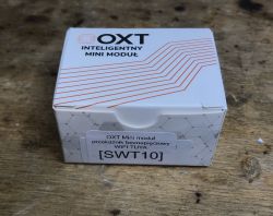
I will show here the interior and the procedure of freeing the OXT SWT10 volt-free relay from the cloud. A volt-free relay is one that does not have a permanent power supply to the output of the relay. The relay output is completely isolated here, so we can successfully control a completely different circuit with it, even a 12V one. This is a completely different situation than in the case of most popular Sonoff/Qiahip/Tuya gadgets, where the most popular versions allow you to conveniently control only mains voltage devices, which also power the system and is routed directly to one of the relay contacts.
Purchase OXT SWT10
I got the OXT SWT10 in a package from a reader, along with other Tuya gadgets for which I had to change the firmware for him, because he is a person who does not even have a soldering iron. The product itself, in turn, is quite popular on the web and is easy to buy in our country. Around PLN 40 is not such a big price at all.
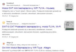
A few screenshots from the sale offer:
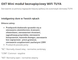
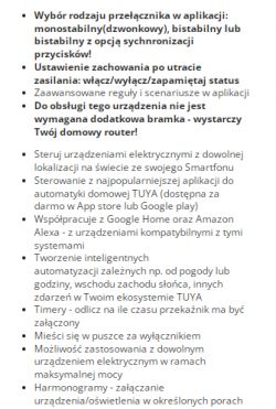
These schedules etc. are in the Tuya application, but I have described it many times, so I will skip it today. Just parameters:
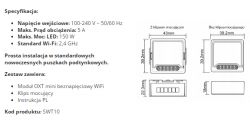
Kit contents
Here are some photos of the packaging (with markings) and the contents of the set:
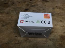
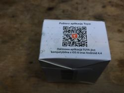
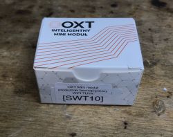
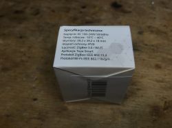
This time quite poor. They didn't even provide screws and double-sided tape.
OXT SWT10 interior
It's time to look inside and upload OpenBeken to free this product from the cloud.
We start by prying the cover:
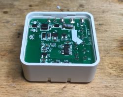
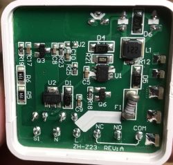
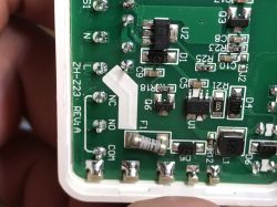
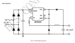
Inside there is a standard power supply for BP2525 and AMS1117-3.3V that gives a stable power supply for the WiFI module.
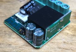
The relay is mounted quite interestingly, because on an additional small PCB:
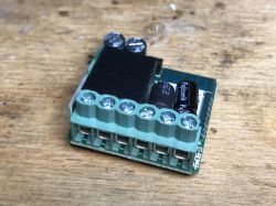
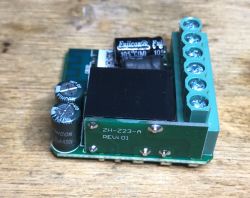
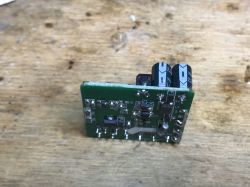
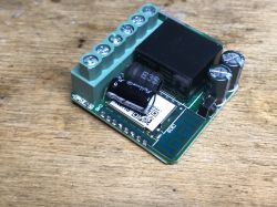
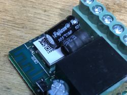
The product is based on the CB3S WiFi module. This time, however, not CB2S. It's probably because the CB2S would be too tall for this case.
Wgrywanie OpenBeken
Programujemy moim BK7231 GUI flasherem:
https://github.com/openshwprojects/BK7231GUIFlashTool
Dokumentacja CB3S szybko nam powie, gdzie są interesujące nas sygnały.
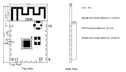
| Pin number | Symbol | I/O type | Function |
| 8 | VCC | P | Power supply pin (3.3V) |
| 9 | GND | P | Power supply reference ground |
| 15 | RXD1 | I/O | UART1_RXD (user serial interface), which corresponds to P10 of the IC. Do not connect it to the VCC. By default, the MCU serial port should be in low-level or high-impedance state. |
| 16 | TXD1 | I/O | UART1_TXD (user serial interface), which corresponds to P11 of the IC. Do not connect it to the VCC. By default, the MCU serial port should be in low-level or high-impedance state. |
In this particular case, no external LDO regulator is needed because the AMS1117-3.3V is on board. You can solder in front of him.
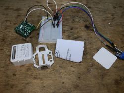
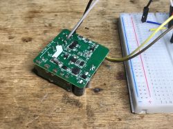
I did not solder the CEN either, I did the RESET by cutting off the power supply (5V) for a moment. Programming went smoothly.
GPIO roles
Otherwise, the OpenBeken template, there is not much to set here:
- LED - P9 (you can set the role of WiFi LED or LED_n to work inversely to the relay)
- switch - ToggleChannelOnToggle - P8
- relay - P6
- push-through on the housing - Button role - P26
It is worth remembering that in OpenBeken you can turn on energy saving on this type of devices using the PowerSave 1 command.
Same in Tuya JSON form:
Code: JSON
And in the form of an OBK template:
Code: JSON
Summary
Another device freed from the cloud. This particular relay was distinguished by the fact that it is "voltage-free", i.e. it does not have a rigidly connected relay output to the network, you can connect a lower voltage receiver there (with galvanic separation) and everything will work properly.
Of course, you could convert an ordinary smart switch to work this way, I've seen some cut the PCB traces to "free" the relay output from 230V, but why make a sculpture? This product costs only PLN 40 and does its job well.
When buying from China, it would probably be even cheaper, but this time we bought in our country and it wasn't that expensive.
Cool? Ranking DIY Helpful post? Buy me a coffee.


