logo elektroda
logo elektroda
X
logo elektroda

Deciphering Pin Configuration & JSON Readout for Marlrin RGBCW Corner Floor Lamp (MOSI/MISO)

bobthemonkee 1017 4
ADVERTISEMENT
  • #1 20660413
    bobthemonkee
    Level 5  

    Greetings!

    I have one of these that I'm trying to figure out...
    https://www.amazon.com/gp/product/B0C53KHS95/ref=ppx_yo_dt_b_search_asin_title?ie=UTF8&psc=1

    So far I have pins 7 and 8 controlling C and W, as the config says. Not sure what ADC does, but it seems to be doing something. And no idea what ctrl_pin is.

    I have attached the flash dump and here is the JSON readout.

    This appears to be similar to this thread (https://www.elektroda.com/rtvforum/topic3982052.html), but doesn't look like it was figured out. Was wondering if there was more I could do to figure out how to get this thing going.

    Thanks in advance!

    {
    	"Jsonver":"1.0.3",
    	"brightmin":"10",
    	"gmwb":"75",
    	"title20":"0",
    	"1err":"50",
    	"totallen":"125",
    	"gmwg":"70",
    	"leaderr":"30",
    	"wfcfg":"spcl_auto",
    	"colormin":"10",
    	"bitseq":"0",
    	"pmemory":"1",
    	"gmkb":"60",
    	"pairt":"18",
    	"cmod":"rgbcw",
    	"slidemod":"2",
    	"micpin":"23",
    	"customcode":"33dd",
    	"rstbr":"50",
    	"0err":"70",
    	"colormax":"100",
    	"c_pin":"7",
    	"module":"CBU",
    	"ctrl_lv":"0",
    	"irpin":"20",
    	"brightmax":"100",
    	"wfct":"3",
    	"pwmhz":"1000",
    	"defbright":"100",
    	"starterr":"30",
    	"rstnum":"3",
    	"rstcor":"c",
    	"sensimax":"300",
    	"micproc":"800",
    	"c_lv":"1",
    	"miso":"17",
    	"mosi":"16",
    	"keyfunc":"0",
    	"irfunc":"1",
    	"brifollow":"1",
    	"ctrl_pin":"26",
    	"adclimit":"2400",
    	"sensimin":"100",
    	"ismusic":"1",
    	"brightstep":"20",
    	"remdmode":"0",
    	"w_lv":"1",
    	"colorpfun":"0",
    	"CS":"15",
    	"gmwr":"100",
    	"gmkg":"60",
    	"onoffmode":"0",
    	"colororder":"0",
    	"w_pin":"8",
    	"LedNum":"25",
    	"irfunset":"[[1",
    	"aging":"0",
    	"rsttemp":"100",
    	"category":"0505",
    	"SCL":"14",
    	"gmkr":"80",
    	"defcolor":"g",
    	"crc":"61",
    	"dns_prio":"0 "
    }

    Device configuration, as extracted from Tuya: 
    - LED Cool (Channel 4) on P7
    - Control Pin (TODO) on P26
    - LED Warm (Channel 5) on P8
    Device seems to be using CBU module, which is using BK7231N.
    And the Tuya section starts, as usual, at 2023424
    

  • ADVERTISEMENT
  • #2 20661229
    p.kaczmarek2
    Moderator Smart Home

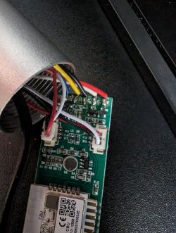
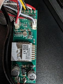
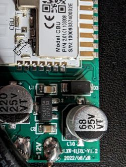
    So this device is also RGB but only C and W are on PWMs? Well, this means it must have some kind of I2C driver chip for the LEDs. We need to know the markings of that chip. Can you provide high-quality photos of the board?
    Helpful post? Buy me a coffee.
  • ADVERTISEMENT
  • #3 20661404
    bobthemonkee
    Level 5  

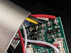
    Here are some pics of the board. Looks like you are right, there is a DI and G controlling colors and individual CW wires, which checks out with the JSON.

    If you have any ideas, please let me know, I will keep tinkering

    Deciphering Pin Configuration & JSON Readout for Marlrin RGBCW Corner Floor Lamp (MOSI/MISO) Deciphering Pin Configuration & JSON Readout for Marlrin RGBCW Corner Floor Lamp (MOSI/MISO) Deciphering Pin Configuration & JSON Readout for Marlrin RGBCW Corner Floor Lamp (MOSI/MISO) Deciphering Pin Configuration & JSON Readout for Marlrin RGBCW Corner Floor Lamp (MOSI/MISO)
  • ADVERTISEMENT
  • #4 20661425
    p.kaczmarek2
    Moderator Smart Home
    Those are SPI pins:
    
    	"miso":"17",
    	"mosi":"16",
    	"CS":"15",
    	"SCL":"14",
    

    Those are P numbers, so 14 is P14, etc.
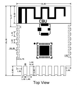
    Here is CBU pinout:
    https://developer.tuya.com/en/docs/iot/cbu-module-datasheet?id=Ka07pykl5dk4u
    Deciphering Pin Configuration & JSON Readout for Marlrin RGBCW Corner Floor Lamp (MOSI/MISO)
    Pin numberSymbolI/O typeFunction
    1P14I/OCommon GPIO, which can be reused as SPI_SCK (Correspond to Pin 11 of the IC)
    2P16I/OCommon GPIO, which can be reused as SPI_MOSI (Correspond to Pin 12 of the IC)
    3P20I/OCommon GPIO (Correspond to Pin 20 of the IC)
    4P22I/OCommon GPIO (Correspond to Pin 18 of the IC)
    5ADCI/OADC, which corresponds to P23 on the internal IC (Correspond to Pin 17 of the IC)
    6RX2I/OUART_RX2, which corresponds to P1 on the internal IC. (Correspond to Pin 28 of the IC)
    7TX2I/OUART_TX2, which is used for outputting logs and corresponds to P0 of the internal IC (Correspond to Pin 29 of the IC)
    8P8I/OSupport hardware PWM (Correspond to Pin 24 of the IC)
    9P7I/OSupport hardware PWM (Correspond to Pin 23 of the IC)
    10P6I/OSupport hardware PWM (Correspond to Pin 22 of the IC)
    11P26I/OSupport hardware PWM (Correspond to Pin 15 of the IC)
    12P24I/OSupport hardware PWM (Correspond to Pin 16 of the IC)
    13GNDPPower supply reference ground
    143V3PPower supply 3V3
    15TX1I/OUART_TX1, which is used for transmitting user data and corresponds to Pin 27 of the IC. For the MCU solution, please refer to CBx Module.
    16RX1I/OUART_RX1, which is used for receiving user data and corresponds to Pin 26 of the IC. For the MCU solution, please refer to CBx Module.
    17P28I/OCommon GPIO (Correspond to Pin 10 of the IC)
    18CENI/OReset pin, low active (internally pulled high), compatible with other modules (Correspond to Pin 21 of the IC)
    19P9I/OCommon GPIO (Correspond to Pin 25 of the IC)
    20P17I/OCommon GPIO, which can be reused as SPI_MISO (Correspond to Pin 14 of the IC)
    21P15I/OCommon GPIO, which can be reused as SPI_CS (Correspond to Pin 13 of the IC)
    Test pointCSNI/OMode selection pin. If it is connected to the ground before being powered on, enter the firmware test mode. If it is not connected or connected to VCC before being powered on, enter the firmware application mode. Correspond to Pin 19 on the internal IC.

    Can you tell me where are those 4 pins connected on your board? Check with multimeter if necessary.
    Helpful post? Buy me a coffee.
  • #5 20911787
    pborrelli
    Level 3  

    Did this ever get figured out? I have a similar RGBW+IC set of lights that I'm trying to get working and am hitting a wall on. I'm looking to learn from what you found out.
ADVERTISEMENT