logo elektroda
logo elektroda
X
logo elektroda

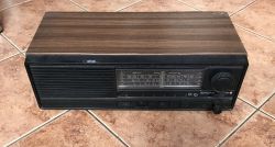
Interior of an old Polish radio receiver UNITRA Sniezka R-207

p.kaczmarek2 14196 97
ADVERTISEMENT
Treść została przetłumaczona polish » english Zobacz oryginalną wersję tematu
  • Interior of an old Polish radio receiver UNITRA Sniezka R-207 .
    Hello my dears .
    In this short topic I would like to present the interior of an old Polish radio receiver UNITRA Sniezka R-207. The receiver presented here I rescued from electro-waste - I don't know how someone could throw it away, it is a good piece of Polish electronics history. It was manufactured in the 1980s/90s. After refreshing (and tuning) it can play nicely again.
    I will also post its schematic diagram and component catalogue notes in the topic.

    Interior of UNITRA Snowball R-207 .
    The radio case is made of veneered chipboard. Only the front is plastic:
    Interior of an old Polish radio receiver UNITRA Sniezka R-207 .
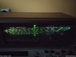
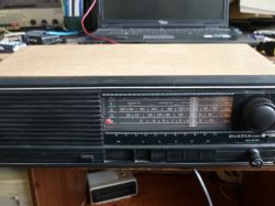
    The front shows the proud inscription "Snow Diora" and we can see the ranges on which we can receive. Tuning is of course done mechanically, with a big knob. Next to it is the volume potentiometer:
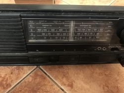
    Interior of an old Polish radio receiver UNITRA Sniezka R-207 .
    The radio has 5 ranges, which are selected using the buttons - K2 and K1 (short wave), S (medium), D (long), U (UKF), the wave ranges shown in the photo above.
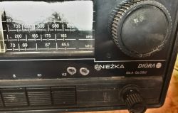
    Interior of an old Polish radio receiver UNITRA Sniezka R-207 .
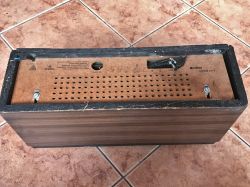
    On the back we have a fibreboard on which there is also information about the specific model (R207):
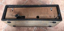
    Interior of an old Polish radio receiver UNITRA Sniezka R-207 .
    Interior of an old Polish radio receiver UNITRA Sniezka R-207 .
    I received the radio in the condition as shown in the pictures. The 220V power cable must have been cut off some time ago, because the copper wires are heavily rusted. In addition, someone must have fiddled something with the speaker connector and added it so that it only holds loosely on the wires:
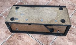
    Interior of an old Polish radio receiver UNITRA Sniezka R-207 .
    The hex screws on the bottom hold the single laminate plate with the electronics inside the case. Two screws on the fibreboard at the back hold this plate - it can be easily removed:
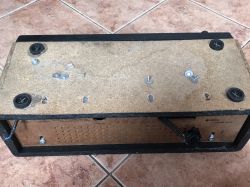
    Interior of an old Polish radio receiver UNITRA Sniezka R-207 .
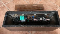
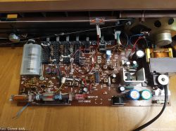
    Rear plate removed:
    Interior of an old Polish radio receiver UNITRA Sniezka R-207 .
    The electrolytic capacitors, which may have to be replaced, are glaringly visible.
    You can already start looking at the interior - you can see that there is a single Tonsil 8Ω speaker inside:
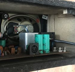
    Interior of an old Polish radio receiver UNITRA Sniezka R-207 .
    Above you can see the distinctive GM545 socket.
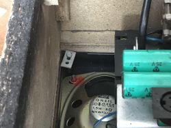
    Interior of an old Polish radio receiver UNITRA Sniezka R-207 .
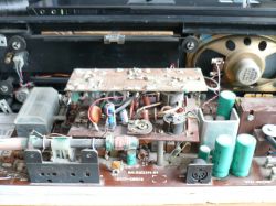
    The electronics PCB is fixed to the front and slides out of the case along with the front:
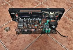
    Interior of an old Polish radio receiver UNITRA Sniezka R-207 .
    In the photo above you can also see the cable and rollers and the tuning carriage - a mechanical arrangement.
    In addition, we can see that someone has rummaged around here before - an additional connector is plugged directly into the speaker.
    The plastic parts holding the laminate look like this up close:
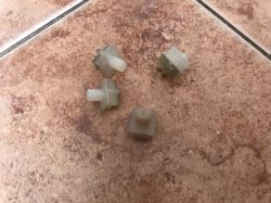
    Interior of an old Polish radio receiver UNITRA Sniezka R-207 .
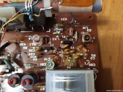
    There is a distinctive ferrite antenna on the board:
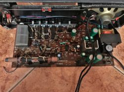
    Interior of an old Polish radio receiver UNITRA Sniezka R-207 .
    Adjustable capacitor used to select the frequency on which to receive:
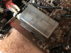
    Interior of an old Polish radio receiver UNITRA Sniezka R-207
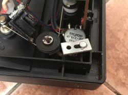
    Potentiometer from the volume knob (manufactured by Telpod, 47kΩ, wired into the loudspeaker amplifier circuit):
    Interior of an old Polish radio receiver UNITRA Sniezka R-207 .
    It may have to be replaced or cleaned - wear and tear on the potentiometer (its carbon tracks) can manifest as crackling in the speakers, among other things.
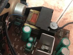
    On the board you can see the fuses and the mains transformer:
    Interior of an old Polish radio receiver UNITRA Sniezka R-207 .
    This mains transformer is probably a TS-6/21.
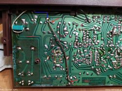
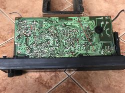
    PCB from underneath:
    Interior of an old Polish radio receiver UNITRA Sniezka R-207 .
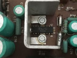
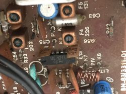
    There are two integrated circuits in the radio. PA210 by CEMI (6W power amplifier):
    Interior of an old Polish radio receiver UNITRA Sniezka R-207 .
    UL1211 (also from CEMI), AM/FM intermediate frequency amplifier:
    Interior of an old Polish radio receiver UNITRA Sniezka R-207 .

    Component schematic and datasheet .
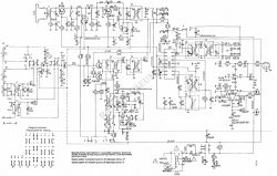
    The schematic of this radio can be found in many places on the web, I am also posting it below for the convenience of readers:
    Interior of an old Polish radio receiver UNITRA Sniezka R-207
    The schematic shows the voltages at certain points, which makes fault diagnosis easier.
    The power amplifier in this schematic is UL1482 (not UL1481), although in my PCB it is PA210.
    Notes of these two ICs:
    UL1482.pdf Download (161.16 kB) .
    UL1211..pdf Download (378.89 kB) .
    BF195 and BF194 transistors are also used in the radio. Transistor catalogue:
    BF194_CEMI...ota.pl.pdf Download (2.13 MB) .
    An AAP153 germanium diode sits in the head:
    AAP153.pdf Download (161.28 kB) .


    Summary .
    I have shown here the interior of an old Polish UNITRA Sniezka R-207 radio receiver. The receiver has not yet been run by me at this point, but perhaps I will get around to it soon. Probably the UKF reception range will have to be tuned as well.
    In the meantime, I invite you to discuss - do you have any experience with this type of radio, maybe some stories or anecdotes? .

    Cool? Ranking DIY
    Helpful post? Buy me a coffee.
    About Author
    p.kaczmarek2
    Moderator Smart Home
    Offline 
    p.kaczmarek2 wrote 11826 posts with rating 9927, helped 564 times. Been with us since 2014 year.
  • ADVERTISEMENT
  • #2 18943838
    szeryf3
    Level 29  
    Cool that you are saving something for posterity. How much of it went into the rubbish.
    Of the rescued ones I have: Diore U2 pcs 2, Jovite 1, well that's what I use every day. Interior of an old Polish radio receiver UNITRA Sniezka R-207 Plus something small Polish transistor from the 80s at work, and a big German one from the 80s too.
  • #3 18943844
    MAT_ ZAJ
    Level 10  
    The PA210 is the export equivalent of the UL 1481/1482. They used whatever they happened to wind up in the assembly :P .
    An external speaker socket added amateurishly and in a rather idiotic way - connecting anything there will be in parallel - in effect reducing the resultant impedance and may lead to damage of the HF amplifier . There were suitable domestically produced speaker sockets with a normally open contact when plugged in - you could cut off the speaker built into the radio in this way.
  • #4 18944089
    pawelr98
    Level 39  
    You will have room to play with when tuning.
    The coils have no core but are air coils. You will have to work hard with the compression and stretching of the heterodyne coil (L3/L4).

    I have a similar head in the DSP-301.
    Here there is no arcz so you can try tuning "from below" at -10.7MHz, which may be more convenient.
    With the standard +10.7MHz, I had to bend the coil a lot to get full range coverage.

    And if a colleague does not have instruments then the RTL-SDR is the most convenient for tuning.
    Low price and no detuning because you don't plug anything into the circuit.
  • #5 18944514
    Janusz_kk
    Level 39  
    p.kaczmarek2 wrote:
    There are electrolytic capacitors that may need replacing.

    Very doubtful, I have repaired these radios, the capacitors have never failed and these will also be good, at most a slight hum will mean that the
    At most, a slight hum will mean that a capacitor from the power supply has dried out a bit. I still have these capacitors and they hold capacitance because I use them for various circuits.
  • #6 18944795
    1 Marcin
    Level 17  
    Hello, at one time I played around a bit with tuning the UKF range, the ukf heads from those years are practically the same, I still have a TARABAN 2 radio.
    Greetings.
  • #7 18945535
    maciekma
    Level 11  
    I was involved in the service for 40 years and you have to admit that there is beauty in simplicity....
  • #8 18945720
    Janusz_kk
    Level 39  
    Well no, it's not simple at all because the pile of filters makes it quite difficult for an amateur to tune, if there were ceramic filters then yes, and there were back in the day.
  • #9 18945742
    żarówka rtęciowa
    Level 37  
    Hello

    pawelr98 wrote:
    You will have room to play with the tuning.
    The coils do not have a core but are air coils. You will have to work hard with the compression and stretching of the heterodyne coil (L3/L4).

    I have a similar head in the DSP-301.
    Here there is no ARCz so you can try tuning "from below" at -10.7MHz, which may be more convenient.
    With the standard +10.7MHz, I had to bend the coil a lot to get the whole range covered.


    The heterodyne coil can be rewound with a new one, to which the capacitance of the capacitor is selected to get the desired tuning bandwidth.

    pawelr98 wrote:
    And if you don't have instruments, the RTL-SDR is the most convenient for tuning.


    A frequency indicator with LED display pulled from an old car radio can be used to tune the heterodyne.

    Janusz_kk wrote:
    Well, it's not simple at all because the pile of filters makes it quite difficult for an amateur to tune
    .

    As far as the intermediate frequency amplifier is concerned, its considerable jitter is the result of spinning anything. In the Snowbird R-502 receiver I was able to tune it using the strong signal of the UKF transmitter and the signal level indicator in it.
  • #10 18945752
    Janusz_kk
    Level 39  
    żarówka rtęciowa wrote:
    As far as the intermediate frequency amplifier is concerned, its considerable jitter is the result of twisting anything.
    .
    I repaired radios for quite a long time in those days, you don't even realise what some people can do to a radio, dislodged and cracked ferrites also happened.

    żarówka rtęciowa wrote:
    In the Snowman R-502 receiver I managed to tune it using the strong signal of the UKF transmitter and the signal level indicator in it.
    .
    Because ukf is easier to tune due to the large number of sufficiently 'strong' stations, it was by ear, because popular radios usually did not have an output indicator.
  • ADVERTISEMENT
  • #11 18945783
    żarówka rtęciowa
    Level 37  
    Hello

    Janusz_kk wrote:
    Because exactly the UKF is easier to tune due to quite a number of stations strong enough, it was tuned by ear because popular radios usually did not have an output indicator.


    Of course, you can still connect a voltmeter to the output of the FM demodulator, which makes tuning much easier.

    One more trick to increase sensitivity, just solder a 12pF ceramic capacitor in parallel to the FM antenna terminals. I did this in the Sudety R-208 radio, it is not present in his schematic and the Snowbird's.
  • #12 18945974
    Gismot
    Level 18  
    The R-207 Snezka and R-208 Sudety radios differ only in the casing - the main PCB is the same. And I would forget the RE-320 Kalenica - the main board is the same as in the R-207 only they added a converter module and a clock.

    Unfortunately, a slight 100Hz hum in them is standard because the power supply is poorly designed, specifically the ground.

    The original design was as follows: bridge rectifier -> m.cz. amplifier -> and only capacitors C75, C76 smoothing the voltage in the power supply. The result: loud hum in the loudspeaker.
    The design error was corrected to some extent by shorting with an additional ground wire.
    I have marked it on the photo:
    Interior of an old Polish radio receiver UNITRA Sniezka R-207 .

    So I wonder why the designers did not redesign the PCB?


    R-208 Sudeten
    Interior of an old Polish radio receiver UNITRA Sniezka R-207 Interior of an old Polish radio receiver UNITRA Sniezka R-207 Interior of an old Polish radio receiver UNITRA Sniezka R-207 .

    ---
    I know a hotel in Zakopane where the rooms are still equipped with R-208 radios, of course with UKF tuning, so the local radio station (Radio Alex) can be listened to - there is a climate :)
  • ADVERTISEMENT
  • #13 18946028
    CHOPIN66
    Level 14  
    There is no point in replacing electrolytes if they are not leaking or swollen, as they are virtually indestructible due to their crude construction.

    ----
    I knew a resort in Mielno where they also had R208's it was in 2007. maybe they are still in stock .
  • ADVERTISEMENT
  • #14 18946426
    NegativeFeedback
    Level 14  
    Gismot wrote:
    .
    Unfortunately, a slight 100Hz hum in them is standard because the power supply is poorly designed, specifically the ground.
    .

    50
  • #15 18946578
    pawelr98
    Level 39  
    żarówka rtęciowa wrote:
    .
    The heterodyne coil can be wound with a new one, to which the capacitance of the capacitor is selected to obtain the desired tuning bandwidth.

    pawelr98 wrote:
    And if a colleague does not have instruments then the RTL-SDR is the most convenient for tuning.


    A frequency indicator with LED display pulled from an old car radio can be used to tune the heterodyne.
    .

    I did the coil winding from scratch once, when in a tambourine (head as in the jubilat) it turned out that the original winding was not in accordance with the documentation (2.5 coils instead of 3.5). It was breaking the heterodyne oscillation and the radio would not tune properly. With the new coil there were no problems with rippling, but it was necessary to give a series capacitor with the heterodyne tuning unit so that the CCIR band could be stretched full-scale.

    In the case of the DSP-301, I did not play with such things.
    There, it was enough to simply insert a trimmer + a small fixed capacitor and the alignment was standard.

    If someone wants to make a coil from scratch, I won't forbid it, especially if you improve the factory and give some core carcass there.

    All sorts of frequency meters need to be plugged into the radio circuit and some (however small) tuning done there. In the case of unshielded heads, it is enough to put your hand or something metallic close to it and it will float. In the case of shielded heads, "contactless" measurement has even more advantages, because we tune with the shield in place, so there is no need to "correct" it after the shield is in place.

    This is why I like this method of measurement. You don't even have to open the radio to know if it's tuned and how accurately the heterodyne was tuned.

    In general, a correctly tuned heterodyne should have no problems receiving today's stations, provided they are not very densely packed.
    At my place, the minimum is 500kHz and the Tamburyn or Duet radios do not cause problems, but Warsaw or Cracow are worse because the stations are packed more densely.

    Unfortunately, the dual-transistor heads of these table-top receivers are not very selective.
  • #16 18946579
    creative1agh
    Level 14  
    We've been using this model for years in the kitchen as our primary playing equipment. After tuning, of course. It has worked for many years, a few years ago I dismantled and washed the volume potentiometer because it was covered in greasy grease and creaked when I adjusted it.
    The radio is not to be disturbed.
  • #17 18946586
    flinc
    Level 28  
    Adds in topic, soldering of 75 Ohm input hot - ground socket
  • #18 18946706
    Gismot
    Level 18  
    flinc wrote:
    Adding in the subject line, adding a 75 Ohm input hot-mass socket
    .
    After this modification the equipment will lose value ;) .

    NegativeFeedback wrote:
    Gismot wrote:
    .
    Unfortunately, a slight 100Hz hum in them is standard because the power supply is poorly designed, specifically the ground.

    50
    .
    This radio has a full-period rectifier in a Graetz bridge circuit, so the capacitors are charged at 100Hz.

    You probably suggested the schematic from #1 post, unfortunately it is from R-206.

    Diagram of R-207, R-208:
  • #19 18946947
    pier
    Level 24  
    With this wooden casing you have gone....
  • #20 18947588
    ml
    Level 30  
    MAT_ ZAJ wrote:
    PA210 is the export equivalent of UL 1481/1482.


    PA210 = TBA810 = MBA810 = UL1481.
    The UL1482 is a completely different IC, equivalent to the TBA820.
  • #21 18947793
    Anonymous
    Level 1  
  • #22 18947931
    p.kaczmarek2
    Moderator Smart Home
    Gismot wrote:
    .
    You probably suggested the schematic from #1 post, unfortunately it is from R-206.

    I think you are indeed correct, although R207 is even carried on this schematic.
    I will correct the first post.

    Koderr wrote:
    You are wrong to think that:
    (...)
    The housings of these radios were made of veneered chipboard
    .
    Fact, I will correct. I guess I was thinking of something else while writing this.
    Helpful post? Buy me a coffee.
  • #23 18948006
    ads
    Level 12  
    Hello
    I would advise against tuning if the receiver actually works and no one has moved on the intermediate frequency filters. I would keep the original parameters and put in a band converter. There used to be plenty of them. Maybe there is one at my place somewhere too? I will look for one.
    It will then be an original in its class.
    Any way you attempt to tune you may not get satisfactory performance.
    Pay attention to the fact:
    CCIR standard - 87.5- 108MHz bandwidth 20.5MHz
    OIRT - 65,5- 74Mhz bandwidth 8,5MHz
    so the converter will cause us to receive only a part of the CCIR band.
    Tuning manually, we can widen the band, but unwinding the inductances of the input circuits as well as the heterodyne (a very invasive operation - it is impossible to restore the previous state even when replacing the coils with others assembled by yourself) and reducing the capacitances of the circuits, so in the L2 circuit C14 I would change to about 8-12pF and in the heterodyne circuit to 6- 10pF.
    Unfortunately, you can't change the capacitance of the rotary capacitor - you can also change it, but it's very troublesome (in the past, for tuning Pi filters of the radio station, we used to take out every other plate, thus reducing the capacitance of the capacitor). - The worst thing is that its initial capacitance simply cannot be changed. inserting a series capacitance does not solve the problem.
    The easiest way to tune the input circuit
    - you simply remove the existing capacitor and insert some for 3-8pF.
    The best way is to insert some rotary capacitor up to 20pF and adjust for maximum signal.
    In some UKF heads I used to be able to get satisfactory CCIR band coverage even without moving the inductors just by changing the capacitance of the capacitors.
    Please write what you have decided on. I keep my fingers crossed.
    But first check the power supply, M.cz. Then, unfortunately, the range switches - they very much liked to snow.
    Especially in smoking users.
    Cool that you feel like playing with it.
  • #24 18948034
    ml
    Level 30  
    Let me disagree with what colleague ads wrote above.
    These receivers are easy to tune, rarely do you need to change coils and if you do, it is to change coils with higher inductance, reducing capacitance of capacitors in resonance circuits which results in broadening the received band and shifting it upwards (CCIR). Unfortunately, the sensitivity and, above all, selectivity of these and similar radios is poor due to the simple ukf heads and HF path. It is possible to change the input transistor of the head to, for example, BF240, but then the head may become excited when tuned to the maximum sensitivity.
  • #25 18948052
    flinc
    Level 28  
    In the heterodyne circuit, capacitors up to 10 pf none are fitted Wdg. SE 2000/4
  • #26 18948091
    Gismot
    Level 18  
    p.kaczmarek2 wrote:
    though R207 is even carried on this diagram.
    .
    It does indeed say R207 in the right hand corner, interesting. So I wonder if this schematic is from a popular magazine, perhaps someone took a swipe.

    There are some differences between the R-206 and R207 radios (more precisely I mean e.g. power supply, m.cz. amplifier)
  • #27 18949007
    Tytus Kosiarski
    Level 16  
    He,he :) I even made a stereo decoder for it in the second half of the 80s, based on UL1621, described some time ago in Radiolektronik, the signals of both channels were output only to the cassette socket. It was great to listen to (and record) Tomasz Beksinski's Stereo Club, Bogdan Fabianski's Record Evenings and Songs on Request and other programmes on Channel 2 of Polish Radio, the only stereo programme at the time (at least in my town).

    I took the signal for the stereo decoder from the middle pin of the UKF switcher and ran it through a preamplifier on two transistors, as the signal level was too low to control the UL1621 directly. The top PCB of the sandwich is the aforementioned preamplifier, while the bottom PCB is the actual stereo decoder.

    Interior of an old Polish radio receiver UNITRA Sniezka R-207 .

    And this is how the radio looked when playing a stereo broadcast.

    Interior of an old Polish radio receiver UNITRA Sniezka R-207 .

    Best regards, KT
  • #28 18949033
    Olkus
    Level 32  
    Tytus Kosiarski wrote:
    He,he :) I even made a stereo decoder for it in the second half of the 80's on UL1621 described some time ago in Radioektronik, the signals of both channels were output only to the cassette socket. It was great to listen to (and record) Tomasz Beksinski's Stereo Club, Bogdan Fabianski's Record Evenings and Songs on Request and other programmes on Channel 2 of Polish Radio, the only stereo programme at the time (at least in my town).

    I took the signal for the stereo decoder from the middle pin of the UKF switcher and ran it through a preamplifier on two transistors, as the signal level was too low to control the UL1621 directly. The top PCB of the sandwich is the aforementioned preamplifier, while the bottom PCB is the actual stereo decoder.

    Interior of an old Polish radio receiver UNITRA Sniezka R-207 .

    And this is how the radio looked when playing a stereo broadcast.

    Interior of an old Polish radio receiver UNITRA Sniezka R-207 .

    Regards, KT
    .

    Well I wouldn't have guessed that something had been reworked if you hadn't written :) . I myself have only two radios Ania R612 and Dorota IC and also a mister hit gramophone. And one tube Philips B4S62A. For the Ania it needs a knob for the range switch. Maybe someone has and wants to sell? Greetings.
  • #29 18950128
    IrekB
    Level 12  
    Tytus Kosiarski wrote:
    I even made a stereo decoder for it in the second half of the 1980s on the UL1621 described some time ago in Radiolektronik, the signals of both channels were brought out only to the cassette socket. It was great to listen to
    .
    I also converted a radio to stereo in the 1980s. I also added a UL1621, but to a "Silesian". In the same way I took the signal out to the tape jack and fed it to a stereo amplifier, I no longer remember what I made the amplifier on. A real stereo radio was beyond the capabilities of a primary school student. Initially I didn't have anything to make filters out of at the decoder output. I remember hearing a 19kHz pilot signal when I put my ear to the speaker.
  • #30 18956687
    James596
    Level 28  
    I have never liked these devices. Poor, lousy sound without any depth to the amount of space they take up.

Topic summary

The discussion centers on the UNITRA Sniezka R-207, a Polish radio receiver from the 1980s/90s, focusing on its interior, tuning, and restoration. The radio features a veneered chipboard case with a plastic front panel marked "Snow Diora," mechanical tuning via a large knob, and a volume potentiometer. Users share experiences rescuing and refurbishing these radios, noting their durability and historical value despite modest sound quality and selectivity. Technical details include the use of air coils (L2, L3, L4) with specific winding turns (e.g., L4 at 3.5 turns with a half tap), and the heterodyne coil requiring careful tuning or rewinding to cover the CCIR band (87.5–108 MHz). The power amplifier often uses UL1481/UL1482 or equivalents like TBA810, with suggestions to replace transistors (e.g., BC211/BC313 with BD139/BD140) and speakers for improved performance. Common issues include a 100 Hz hum caused by power supply grounding design, which can be mitigated by additional grounding wires or disconnecting the incandescent bulb circuit. Electrolytic capacitors, especially from Elwa, generally remain in good condition unless exposed to adverse environments, but some users recommend checking and replacing those with high ESR. Modifications such as adding a 0.47 µF polyester capacitor across rectifier diodes help suppress high-frequency interference. The discussion also covers tuning techniques using frequency indicators, RTL-SDR devices, and voltmeters on the FM demodulator output. Some users caution against invasive tuning that alters original parameters, suggesting band converters for adapting to different frequency standards (OIRT vs. CCIR). The thread includes comparisons with other Polish models (R-208 Sudety, R-206 Snowbird, Taraban series) and mentions stereo decoder modifications using UL1621 ICs. The overall consensus appreciates the radios' simplicity, durability, and cultural significance, despite limitations in audio fidelity and component quality compared to Western equipment of the era.
Summary generated by the language model.
ADVERTISEMENT