logo elektroda
logo elektroda
X
logo elektroda

[BK7231N] Teardown of Zemismart TUYA WiFi Ceiling Lamp 34W with CCT RGB Colorful Back Light

MnM1 2034 14
ADVERTISEMENT
  • Helpful post
    #1 20732603
    MnM1
    Level 10  
    Hi,

    Below is my journey to free up the Zemismart TUYA WiFi Ceiling Lamp 34W with CCT RGB Colorful Back Light from the Tuya cloud.

    Part 1 - Preparation

    AliExpress device link: Link

    Some pictures of the device:
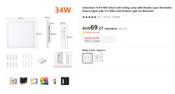
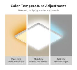
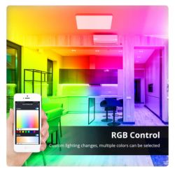
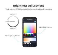
    Zemismart TUYA WiFi Ceiling Lamp 34W with RGB Three lighting options of a ceiling LED lamp: warm, white, and cold light. Interior of a room with an RGB ceiling light featuring color-changing options, controlled via a smartphone app. Smartphone app showing brightness adjustment for a smart home ceiling light.

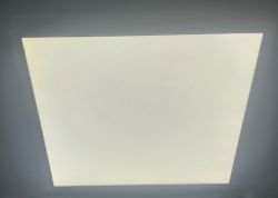
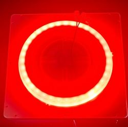
    Below are some pictures of the actual device. Both the white LEDs and the RGB ones are very bright (a bit hard to tell from the pictures but they are).
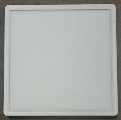
    Square LED ceiling lamp in white color. Square LED ceiling lamp with central light. Square ceiling lamp emitting bright white light. Ceiling lamp with brightly glowing LED ring and red background.

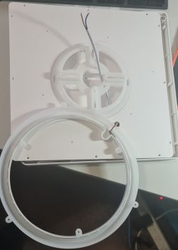
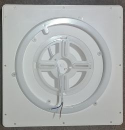
    Opening the device is very easy - a few screws and then the lid can come off.
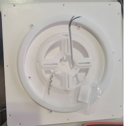
    Image of the underside of a round ceiling lamp with the cover removed, showing wires, screws, and plastic components.

    Image of Zemismart TUYA ceiling lamp with open casing and visible wires.


    After taking the cover off (be careful not break the wires when taking off the cover) this is what we find inside:

    - White LEDs:

    Close-up of an LED strip mounted on a circuit board with visible technical markings.

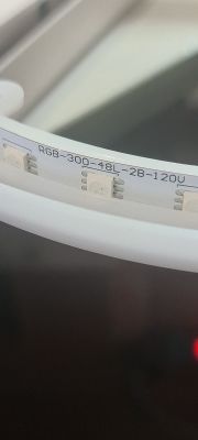
    - RGB LEDs:

    Close-up of an RGB-300-48L-2B-120V LED strip showing several diodes on a white base.

    Below is a picture with an overview of the circuit board:
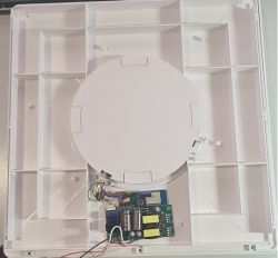
    Interior of Zemismart TUYA WiFi Ceiling Lamp 34W with the cover removed, showing the circuit board and wiring.

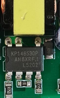
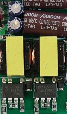
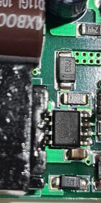
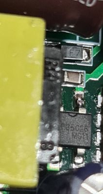
    Also some closeup pictures of the components on the circuit board:
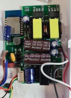
    Close-up of a circuit board with various components. Close-up of electronic components on a printed circuit board. Close-up of components on the Zemismart ceiling lamp circuit board. Close-up of PCB components with markings on the integrated circuits Close-up of PCB components: visible markings on a microchip and other elements.

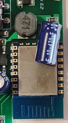
    The Tuya CB3S module - there are no markings on the CB3S Module at all. In the second picture you can notice that I have gently pushed the capacitor (assume it is a capacitor :) ) a little bit out of the way to expose the CB3S module connections.
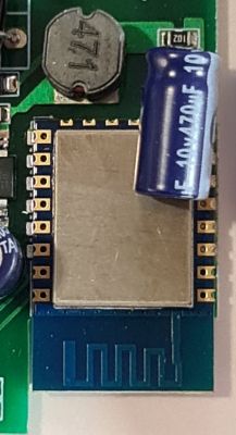
    Close-up of a Tuya CB3S module on a circuit board. Tuya CB3S module on a circuit board with a capacitor

    Since the Tuya module has been identified as a Tuya CB3S module the device will need to be flashed with BK7231N
    Below are some pictures from a test module that I had which further strengthen the case that it is a Tuya CB3S module:
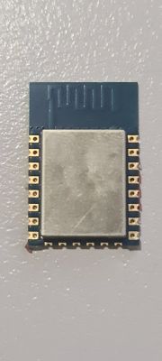
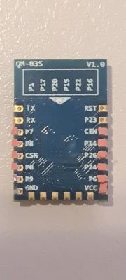
    Tuya CB3S Module QN-03S V1.0 module with pin markings.

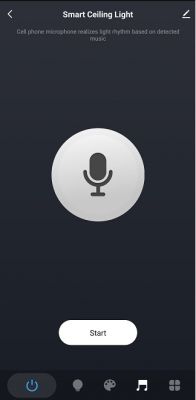
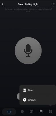
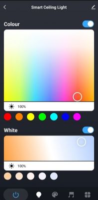
    I have added the light to Tuya Smart Life. Below are some screenshots of what options the device has in the Tuya app:
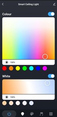
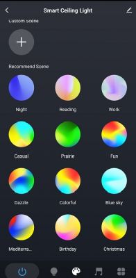
    Tuya Smart Life app interface for ceiling light color adjustment. Screenshot of Smart Ceiling Light app with various lighting scenes. Screenshot of a mobile app for controlling smart ceiling light. Screenshot of the Smart Ceiling Light app with a microphone icon and Timer and Schedule options. Device update screen indicating no updates available.

    Through Tuya IoT I was able to get the DP IDs for the light (but I am not sure if Tuya MCU is actually used on this device):
    {
      "result": {
        "properties": [
          {
            "code": "switch_led",
            "custom_name": "",
            "dp_id": 20,
            "time": 1694525805773,
            "value": true
          },
          {
            "code": "work_mode",
            "custom_name": "",
            "dp_id": 21,
            "time": 1694524999630,
            "value": "white"
          },
          {
            "code": "bright_value",
            "custom_name": "",
            "dp_id": 22,
            "time": 1694524999630,
            "value": 1000
          },
          {
            "code": "temp_value",
            "custom_name": "",
            "dp_id": 23,
            "time": 1694524999630,
            "value": 1000
          },
          {
            "code": "colour_data",
            "custom_name": "",
            "dp_id": 24,
            "time": 1694524999630,
            "value": "000003e803e8"
          },
          {
            "code": "scene_data",
            "custom_name": "",
            "dp_id": 25,
            "time": 1694524999630,
            "value": "000e0d0000000000000000c803e8"
          },
          {
            "code": "countdown",
            "custom_name": "",
            "dp_id": 26,
            "time": 1694524999630,
            "value": 0
          },
          {
            "code": "music_data",
            "custom_name": "",
            "dp_id": 27,
            "time": 1694524996077,
            "value": ""
          },
          {
            "code": "control_data",
            "custom_name": "",
            "dp_id": 28,
            "time": 1694524996077,
            "value": ""
          },
          {
            "code": "mix_rgbcw",
            "custom_name": "",
            "dp_id": 51,
            "time": 1694525805471,
            "value": "AAUAAAPoA+gD6AOE"
          }
        ]
      },
      "success": true,
      "t": 1694526329122,
      "tid": "a2946995517211eeb3f09e6a0abc163a"
    }


    These are the "tools" that I will use to flash OBK to this device:

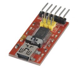
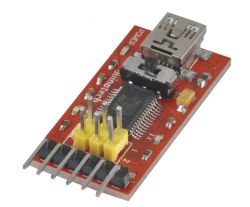
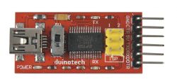
    1. UART 3.3V and 5V (selectable)
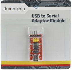
    Duinotech USB to Serial Adapter Module in packaging. Communication module with micro USB port and pin header. Red USB to UART adapter with pin headers and a microchip. Duinotech USB-TTL adapter with GND, CTS, 5V, TXD, RXD, DTR connections.

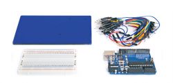
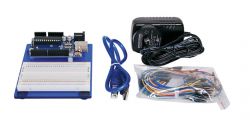
    2. Arduino Uno R3 - I have used a starter kit with mains power supply
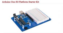
    Arduino Uno R3 platform starter kit with breadboard. Arduino Uno starter kit with breadboard and wires Arduino Uno kit with breadboard, USB cable, and wires

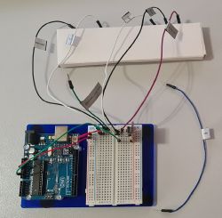
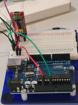
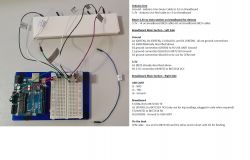
    Below are some pics on how I put the UART and Arduino Uno together:
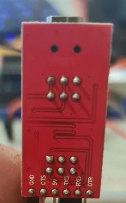
    Close-up of an electronic module with visible pins and traces on a red background. Image of an Arduino Uno R3 module connected to a breadboard with wires, used for flashing a device. Arduino Uno set with connected wires and a breadboard.

    Image of Arduino Uno wiring with a breadboard and descriptions of connections to the Tuya module.

    Some notes for beginners like me :) on the above setup:
    - had to use additional power source as UART will not provide sufficient power
    - I tried intially to get power from the 5V pin on UART and use a 3.3V LDO but that did not work for me. So I got the Arduino Uno R3 kit that is powered with a mains external power supply
    - Ground had to be connected from the Arduino Uno to the chip and the UART

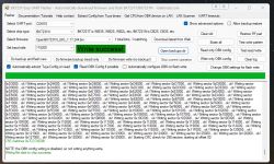
    3. BL7231 Easy UART Flasher
    I will be using used version 1.1.1 on a Windows PC
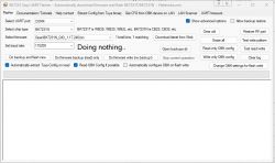
    BK7231 Easy UART Flasher interface on computer screen

    Stay tuned for Part 2 - the OBK flashing process.

    Added after 10 [hours] 15 [minutes]:

    Part 2 - Flashing OBK

    As you can see in the picture below the Tuya CB3S module actually has some holes on the side.
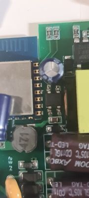
    Close-up image of the Tuya CB3S module on a printed circuit board.

    So instead of taking the whole PCB out and solder wires I have decided to leave it in place and use the Arduino wires to push them slightly in, just enough that they stay put in the holes and don't actually come out.
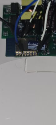
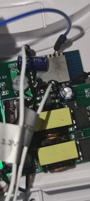
    Close-up of Tuya CB3S module connected with wires. Close-up of an electronic circuit with wires and capacitors on a PCB.

    In the picture below everything is connected and powered up.
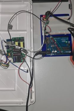
    Electronic module connected to an Arduino board.

    Next I start BK7231 Easy UART Flasher on my Windows PC
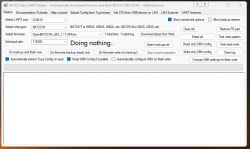
    Screenshot of the BK7231 Easy UART Flasher program with settings

    Started to do a read/write test (and in the process I had to quickly short the CEN wire to the Ground wire). The test completed successfuly.
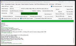
    BK7231 Easy UART Flasher screen with a reading success message.

    Next step was to select the Do firmware backup (read) only in BK7231 Easy UART Flasher. Original Tuya backup completed successfully. Backup file is attached below.
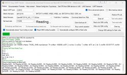
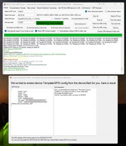
    BK7231 Easy UART Flasher panel on Windows PC displaying options and read flash progress.

    BK7231 Easy UART Flasher interface successfully reading data.

    Next I have selected Do firmware write (no backup) to flash the device with OpenBK7231N_QIO_1.17.244.bin file. The flash was successful.
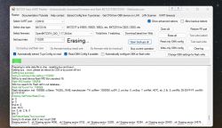
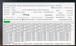
    BK7231 Easy UART Flasher software executing an erase operation. BK7231 Easy UART Flasher interface on a computer with a flashing process log. Screenshot of BK7231 Easy UART Flasher program showing write success.

    I have then removed all the wires from the device and put its cover back and tightened the screws. Next I have connected power to the device.
    I saw its AP, connected to it and added the WIFI configuration. After the reboot the device was on my network and I could connect to it web interface
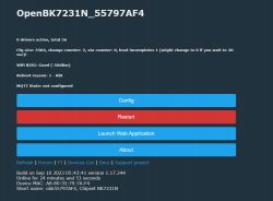
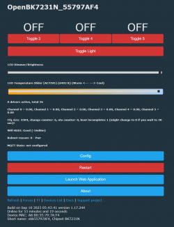
    Screenshot of the OpenBK7231N interface after flashing.

    Stay tuned for Part 3 - Device Configuration.
    Do you have a problem with Arduino? Ask question. Visit our forum Arduino.
  • ADVERTISEMENT
  • Helpful post
    #2 20733872
    MnM1
    Level 10  
    Part 3 - Device Configuration

    As you can see from the Tuya app screenshot this device has 2 individual configurations, 1 for the white LEDs and another for the RGB LEDs.

    Screenshot of the Tuya app showing smart ceiling light configurations.

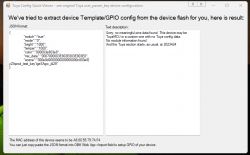
    Also the GPIO config doesn't look like it had any meaningful information in it:

    Screenshot from Tuya Config Quick Viewer showing device GPIO configuration.

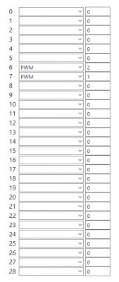
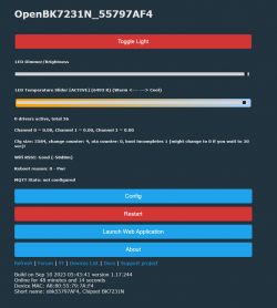
    So through some trial and error I have managed to find the configuration for the white LEDs. With it I can toggle ON/OFF, control the brightness and temperature of the white LEDs.

    Screenshot of a configuration table with GPIO settings for a device.
    Screenshot of OpenBK7231N application showing LED configuration options.

    With the RGB LEDs things are getting more complex, at least for me.
    I have figured that if I set P8, 24 and 26 to LEDs at least I can confirm that I got the right pins. The result is:

    P8 = 3 = RED Color
    P24 = 4 = GREEN Color
    P26 = 5 = BLUE Color

    So at least I got the pins and color correct. However this is not how the configuration should be because I get 3 extra individual toggle buttons on the web interface. There is no brightness or color picker at all:

    Screenshot of the OpenBK7231N application with LED configuration options.

    What I think we should have there is a another toggle button for the RGB LEDs with its own brightness and RGB color picker.

    @p.kaczmarek2 - I might need your assistance to finish off the configuration of this device as I have no idea how to make the above happen. As mentioned white LEDs are working perfect is just the RGB ones that are not.
  • ADVERTISEMENT
  • #3 20733928
    p.kaczmarek2
    Moderator Smart Home
    Hello, what is the expected use case of the ability to set the CCT and RGB modes independently? The following is currently not officially supported, because once you set 5 PWM pins, OBK tries to enable the classic RGB + CCT controller where you have to switch one of the two modes.
    Helpful post? Buy me a coffee.
  • #4 20733951
    MnM1
    Level 10  

    That is how the device works with the Tuya firmware. So it will be good to have it work the same with OBK.
    If I set all the pins to PWM, there are a few things wrong with it:

    - One cannot independently control the on/off toggle of the white light and RGB ones as per Tuya firmware.
    - After you toggle the light on, if the dimmer/brightness is used, it switches off the white LEDs.
    - Similarly, for the temperature slider, if it turns off the white light.
    - The RGB color picker actually changes the white light temperature - the LEDs' color does not change at all.
    - The RGB LEDs are always red - I could not change them to another color.

    Maybe there are more issues, but this is what I have picked up through my testing.
  • #5 20734065
    p.kaczmarek2
    Moderator Smart Home
    Alternatively you can enable "show raw PWMs" mode, but that is usually useful only for debugging.
    Helpful post? Buy me a coffee.
  • #6 20734396
    MnM1
    Level 10  

    I just quickly tried that (enable Flag 3).

    It has 5 sliders that will control the lights.

    The top 2 sliders will control the white light, achieving in a way what the previous configuration did.
    The last 3 sliders sort of equal an RGB picker but in a weird way :)
    There are no on/off toggle buttons.

    Any chance you can have OBK support the functions as they were in the Tuya firmware?
  • #7 20736142
    MnM1
    Level 10  
    @p.kaczmarek2 - anything you can do to have this device supported in OBK? I really don't wanna got back to Tuya firmware.

    Added after 1 [hours] 16 [minutes]:

    Looks like Tasmota has this supported:

    https://templates.blakadder.com/taloya_GA300-24W-AI-WEMG.html

    "To enable independent handling of RGB and white channels the following must be run: SetOption37 128

    To enable the second PWM to control the color temp the following must be run: SetOption92 ON”

    Maybe it will make it easier to migrate the same config in OBK?
  • ADVERTISEMENT
  • #8 20739320
    MnM1
    Level 10  

    Installed ESPHome on this device and it is fully supported - can individually control the white LEDs and RGB LEDs.

    It is OK for now but I would like to come back to OBK when this device will be supported.
  • #9 20740047
    ferbulous
    Level 18  
    Don't RGBCW pins usually configured like this?

    P8 = 1 = RED Color
    P24 = 2 = GREEN Color
    P26 = 3 = BLUE Color
    P7 = 4 = Cold
    P6 - 5 = Warm
  • ADVERTISEMENT
  • #10 20740367
    MnM1
    Level 10  
    Yes - but is still a single toggle button for the 2 individual lights.
  • #11 20843813
    tmfinnell
    Level 3  

    Hi,

    My lamp had the same setup with the mix_rgbcw. I made some progress and have a (somewhat) working custom component that lets me drive the two lights individually like in the native tuya application. I thought you might find it useful, I stumbled upon this thread when researching the datapoint

    https://github.com/taylorfinnell/xmcosy-esphome
  • #12 20843814
    MnM1
    Level 10  

    I have managed to get this going with ESPHome and it works as it was working on Tuya.
    Let me know if you want the YAML.
  • #13 20843818
    tmfinnell
    Level 3  

    Yes please, seeing the yaml would be great. Thank you!
  • #14 20843903
    MnM1
    Level 10  
    Here is the relevant section of the yaml:

    bk72xx:
      board: cb3s
    
    output:
      - platform: libretiny_pwm
        id: output_red
        pin: GPIO8
        max_power: 100%
        frequency: ${frequency_rgb}
      - platform: libretiny_pwm
        id: output_green
        pin: GPIO24
        max_power: 100%
        frequency: ${frequency_rgb}
      - platform: libretiny_pwm
        id: output_blue
        pin: GPIO26
        max_power: 100%
        frequency: ${frequency_rgb}
      - platform: libretiny_pwm
        id: output_cold_white
        max_power: 100%
        frequency: ${frequency_cw}
        pin: GPIO7
      - platform: libretiny_pwm
        id: output_warm_white
        pin: GPIO6
        max_power: 100%
        frequency: ${frequency_ww}
    
    light:
      - platform: cwww
        name: ${device_name_white}
        id: ${device_id_white}
        cold_white: output_cold_white
        warm_white: output_warm_white
        cold_white_color_temperature: 6536 K
        warm_white_color_temperature: 2000 K
        constant_brightness: false
        gamma_correct: 0
        default_transition_length: 0.1s
        restore_mode: RESTORE_DEFAULT_ON
        on_turn_on:
          - globals.set:
              id: last_light_state
              value: "true"
        on_turn_off:
          - globals.set:
              id: last_light_state
              value: "false"
      - platform: rgb
        name: ${device_name_rgb}
        id: ${device_id_rgb}
        red: output_red
        green: output_green
        blue: output_blue
        default_transition_length: 0.1s
        restore_mode: RESTORE_DEFAULT_OFF
        on_turn_on:
          - globals.set:
              id: last_light_state
              value: "true"
        on_turn_off:
          - globals.set:
              id: last_light_state
              value: "false"


    You might to tweak it to suit your own config.
  • #15 20845426
    tmfinnell
    Level 3  

    Awesome, thank you! I could never get PWM to work for me on any pin, I'll give it another go!

Topic summary

The discussion revolves around the process of freeing the Zemismart TUYA WiFi Ceiling Lamp 34W with CCT RGB Colorful Back Light from the Tuya cloud. Users share their experiences with device teardown, configuration, and control of the white and RGB LEDs. Initial attempts to configure the device using OBK (OpenBeken) firmware reveal issues with independent control of the white and RGB channels, leading to unexpected behavior such as toggling off the white LEDs when adjusting brightness. Some users suggest using ESPHome, which allows for full control of both LED types, and share YAML configurations for successful implementation. The conversation also touches on the potential for Tasmota firmware to support independent RGB and white channel control.
Summary generated by the language model.
ADVERTISEMENT