Jasco Enbrighten Cafe WiFi light teardown and analyzing [WB3S-IPEX]
My goal is to get all functions of these lights working locally in home assistant.
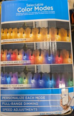
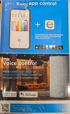
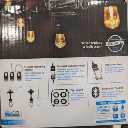
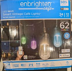
Jasco Enbrighten Café WiFi lights are sold in 12 and 24 strand sets. This teardown is for the 12-strand set, but I presume the 24 strand set is similar. They are controlled by the Tuya cloud with a custom app written by Enbrighten, but of course can also be fully controlled by Tuya Smart which is what I will be using in the teardown.
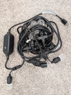
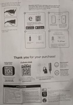
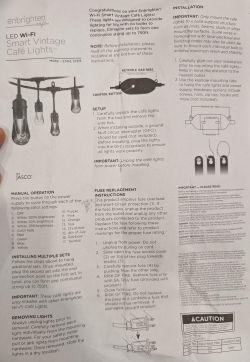
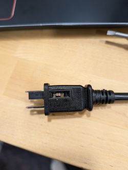
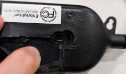
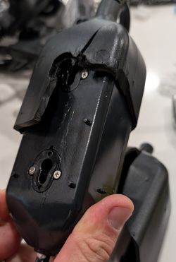
The plug on the power cord has a 250V5A glass fuse. The plug connects to a large enclosure by 18" of 18AWG 2-wire cable. The enclosure is wrapped in thick rubber via an injection molding process - presumably for waterproofing. The rubber was thick and difficult to cut, but thankfully not adhered to the plastic enclosure. Once the rubber was removed we can see several screws that need to be removed to gain access.


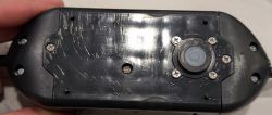
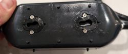
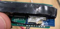
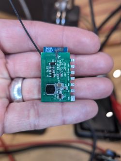
The enclosure contains the power supply, a daughterboard containing a Tuya WB3S-IPEX wifi module with external antenna and an unlabeled MCU, and a 2 wire button that shorts to enter pairing mode (long-press) or manually cycle through colors (short-press). The motherboard is secured to the bottom of the enclosure with two screws and was then filled with 10mm of epoxy - presumably for waterproofing. Note in the last photo I had already removed the wiring going to the lights and installed header pins.

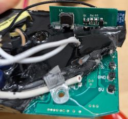
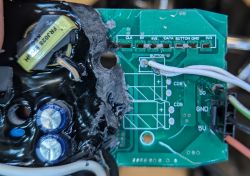
The hard epoxy obscured almost everything. It was very difficult to remove the motherboard from the enclosure. After much prying and cutting I was able to remove it, but in the process I damaged part of the high voltage power supply. Once removed from the enclosure, I was able to use a heat gun, knives, scrapers, and plastic trim tools to remove enough epoxy from the motherboard to see the necessary low voltage components. I discovered I was able to back feed 5V and ground on the low voltage wires heading to the lights to get everything to function - hooray! I plan to repair the power supply or just feed the lights with an external supply.
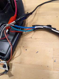
The other end of the enclosure connects to the lights via a main cable. The main cable is 5-wire 18AWG and very thick. Two wires (black and white) are mains passthrough to the female plug on the end of the strand. The other three are 5V (red), ground (green), and data (blue). Each bulb tees off the main cable with a smaller diameter 4-wire 20AWG cable containing 5V, ground, and two data lines for daisy chaining Din and Dout to each bulb.
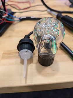
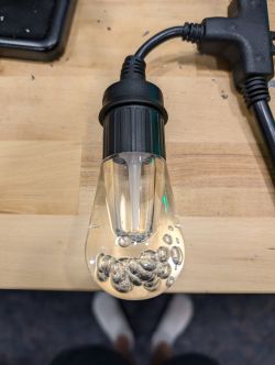
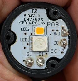
Each bulb unscrews to reveal a translucent dispersion lens secured to the base by three screws. There is a rubber gasket between the lens and base. The LED PCB has a RBG LED and a white LED. We can also see 5V, Din, Dout, and ground terminations from the 4-wire cable. The backside of the PCB contains an IC labeled OT1024B and what looks like FAZ1-7491MT along with various resisters and components. I was unable to find documentation on the IC. If you can find something, please share!
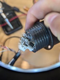
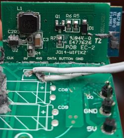
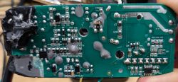
Interestingly, there is also the same OT1024B IC on the backside of the motherboard which is where some of the Tuya+MCU daughterboard Data pin connects. Probing the IC shows it is a 4-channel RGBW driver using an unknown protocol with the voltages below. I don't have a proper Oscilliscope and wasn't confident that my Arduino scope (https://projecthub.arduino.cc/Ameduino/diy-arduino-oscilloscope-56d4c0) output was accurate. I suspect the OT1024B is a generic IC using a common protocol, but have yet to discover which one. If you know, please share!
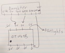
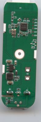
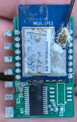
The Tuya+MCU daughterboard has 7 pads that physically pierce the motherboard and are soldered to corresponding pads on the backside of the motherboard. I removed the assembly to clean up with some IPA and photograph. I then reattached it at a better angle in order to access all the Tuya pads. We can clearly see the part number for the Tuya Wifi chip is WB3S-IPEX which is detailed at https://developer.tuya.com/en/docs/iot/wb3sipex-module-datasheet?id=K9irq0laun21z
At this point, I soldered wires to TXD1, RXD1 and GND then used two ESP32s in UART passthrough mode with TuyaMCUAnalzer.
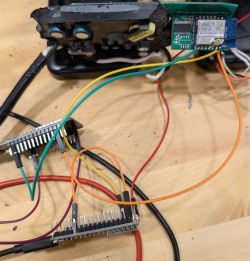
Upon power-up we see the MCU info: {"p":"2q0e3h56uzb0sxbv","v":"0.2.11","m":0}. We also see two useful dpIds showing current value of the lights:
dpId=104 Str V=111111111111
- Individual bulb on/off as ASCII 1 or 0:
dpId=106 Str V=9001f403e8
- Mode, effect, speed, brightness and optional channel value (appended and delimited as ASCII 0#, max three).
- I cycled through the various colors, presets and customizations and noticed the following patterns below. The PDF has a ton of examples from the analyzer.
Mode
0: Fade
1: Blink
2: Twinkle
3: Rainbow
4: Red White Blue
5: Red White Green
6: Mardi Gras
7: Valentines
8: Autumn
9: St. Patricks
a: Spring
b: Customize (probably b-f are custom save banks)
Effect
0: Solid (ignore mode and next 4 characters which are speed)
1: Twinkle
3: Pulse
4: Wave Chase
5: Chase
6: Wave
7: Fade
Speed
03e8 - 100%
01f4 - 50%
000a - 1%
Brightness
03e8 - 100%
01f4 - 50%
000a - 1%
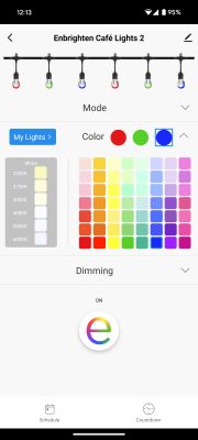
I thought it'd be helpful to show some app screenshots.
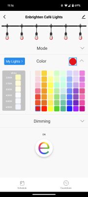
1. Colors section. Note one red orb and 62 colors per the box. Also note the My Lights button explained in 2. This changes dpId 106.
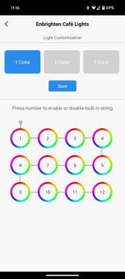
2. My lights screen where you can add up to three orbs and set color for the repeating pattern, or toggle power to each bulb. This changes dpId 104.
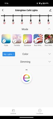
3. Mode which contains presets (effects, brightness and speed manipulations). This changes dpId 106.
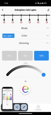
4. Dimming with range of 1%-100%. This changes dpId 106.
At this point I could use some guidance on next steps. I have some questions:
1. Can anyone tell by what I captured if this is a standard RGBW protocol?
2. Do I have enough data to recreate everything? I have four strands of lights, so can flash one and tear down another if I need more data.
3. Does BK7231Flasher support the WB3S-IPEX Tuya chip? I know WB3S is supported, but not sure if the IPEX piece matters or not. I know I'll have to detach the WB3S chip from the daughterboard since the MCU will interfere.
Note I tried to connect the lights to an ESP32 running WLED, but was unable to get them to turn on or do anything. I suspect it's because I don't have a level shifter inline and have ordered some. I'd like to just reflash the Tuya chip and learn if folks are willing to help!
My goal is to get all functions of these lights working locally in home assistant.
Jasco Enbrighten Café WiFi lights are sold in 12 and 24 strand sets. This teardown is for the 12-strand set, but I presume the 24 strand set is similar. They are controlled by the Tuya cloud with a custom app written by Enbrighten, but of course can also be fully controlled by Tuya Smart which is what I will be using in the teardown.


The plug on the power cord has a 250V5A glass fuse. The plug connects to a large enclosure by 18" of 18AWG 2-wire cable. The enclosure is wrapped in thick rubber via an injection molding process - presumably for waterproofing. The rubber was thick and difficult to cut, but thankfully not adhered to the plastic enclosure. Once the rubber was removed we can see several screws that need to be removed to gain access.


The enclosure contains the power supply, a daughterboard containing a Tuya WB3S-IPEX wifi module with external antenna and an unlabeled MCU, and a 2 wire button that shorts to enter pairing mode (long-press) or manually cycle through colors (short-press). The motherboard is secured to the bottom of the enclosure with two screws and was then filled with 10mm of epoxy - presumably for waterproofing. Note in the last photo I had already removed the wiring going to the lights and installed header pins.


The hard epoxy obscured almost everything. It was very difficult to remove the motherboard from the enclosure. After much prying and cutting I was able to remove it, but in the process I damaged part of the high voltage power supply. Once removed from the enclosure, I was able to use a heat gun, knives, scrapers, and plastic trim tools to remove enough epoxy from the motherboard to see the necessary low voltage components. I discovered I was able to back feed 5V and ground on the low voltage wires heading to the lights to get everything to function - hooray! I plan to repair the power supply or just feed the lights with an external supply.


The other end of the enclosure connects to the lights via a main cable. The main cable is 5-wire 18AWG and very thick. Two wires (black and white) are mains passthrough to the female plug on the end of the strand. The other three are 5V (red), ground (green), and data (blue). Each bulb tees off the main cable with a smaller diameter 4-wire 20AWG cable containing 5V, ground, and two data lines for daisy chaining Din and Dout to each bulb.


Each bulb unscrews to reveal a translucent dispersion lens secured to the base by three screws. There is a rubber gasket between the lens and base. The LED PCB has a RBG LED and a white LED. We can also see 5V, Din, Dout, and ground terminations from the 4-wire cable. The backside of the PCB contains an IC labeled OT1024B and what looks like FAZ1-7491MT along with various resisters and components. I was unable to find documentation on the IC. If you can find something, please share!


Interestingly, there is also the same OT1024B IC on the backside of the motherboard which is where some of the Tuya+MCU daughterboard Data pin connects. Probing the IC shows it is a 4-channel RGBW driver using an unknown protocol with the voltages below. I don't have a proper Oscilliscope and wasn't confident that my Arduino scope (https://projecthub.arduino.cc/Ameduino/diy-arduino-oscilloscope-56d4c0) output was accurate. I suspect the OT1024B is a generic IC using a common protocol, but have yet to discover which one. If you know, please share!

The Tuya+MCU daughterboard has 7 pads that physically pierce the motherboard and are soldered to corresponding pads on the backside of the motherboard. I removed the assembly to clean up with some IPA and photograph. I then reattached it at a better angle in order to access all the Tuya pads. We can clearly see the part number for the Tuya Wifi chip is WB3S-IPEX which is detailed at https://developer.tuya.com/en/docs/iot/wb3sipex-module-datasheet?id=K9irq0laun21z
At this point, I soldered wires to TXD1, RXD1 and GND then used two ESP32s in UART passthrough mode with TuyaMCUAnalzer.


Upon power-up we see the MCU info: {"p":"2q0e3h56uzb0sxbv","v":"0.2.11","m":0}. We also see two useful dpIds showing current value of the lights:
dpId=104 Str V=111111111111
- Individual bulb on/off as ASCII 1 or 0:
dpId=106 Str V=9001f403e8
- Mode, effect, speed, brightness and optional channel value (appended and delimited as ASCII 0#, max three).
- I cycled through the various colors, presets and customizations and noticed the following patterns below. The PDF has a ton of examples from the analyzer.
Mode
0: Fade
1: Blink
2: Twinkle
3: Rainbow
4: Red White Blue
5: Red White Green
6: Mardi Gras
7: Valentines
8: Autumn
9: St. Patricks
a: Spring
b: Customize (probably b-f are custom save banks)
Effect
0: Solid (ignore mode and next 4 characters which are speed)
1: Twinkle
3: Pulse
4: Wave Chase
5: Chase
6: Wave
7: Fade
Speed
03e8 - 100%
01f4 - 50%
000a - 1%
Brightness
03e8 - 100%
01f4 - 50%
000a - 1%
I thought it'd be helpful to show some app screenshots.
1. Colors section. Note one red orb and 62 colors per the box. Also note the My Lights button explained in 2. This changes dpId 106.

2. My lights screen where you can add up to three orbs and set color for the repeating pattern, or toggle power to each bulb. This changes dpId 104.

3. Mode which contains presets (effects, brightness and speed manipulations). This changes dpId 106.

4. Dimming with range of 1%-100%. This changes dpId 106.

At this point I could use some guidance on next steps. I have some questions:
1. Can anyone tell by what I captured if this is a standard RGBW protocol?
2. Do I have enough data to recreate everything? I have four strands of lights, so can flash one and tear down another if I need more data.
3. Does BK7231Flasher support the WB3S-IPEX Tuya chip? I know WB3S is supported, but not sure if the IPEX piece matters or not. I know I'll have to detach the WB3S chip from the daughterboard since the MCU will interfere.
Note I tried to connect the lights to an ESP32 running WLED, but was unable to get them to turn on or do anything. I suspect it's because I don't have a level shifter inline and have ordered some. I'd like to just reflash the Tuya chip and learn if folks are willing to help!


