logo elektroda
logo elektroda
X
logo elektroda

LED WiFi RGBCW Tuya - teardown, BK7231N, programming with my Tasmota replacement

p.kaczmarek2 21078 8
ADVERTISEMENT
Treść została przetłumaczona polish » english Zobacz oryginalną wersję tematu
  • LED WiFi RGBCW Tuya - teardown, BK7231N, programming with my Tasmota replacement
    Hello all, it's time to flash another BK7231N device with my Tasmota clone and pair it with my Home Assistant.
    This time it will be a smart LED bulb by Tuya, offering a wide range of colors, RGB and cold and warm white. 12W, E27. I will start with a teardown, then I will show how to hook up USB to UART programmer and finally I will also check its power consumption in standby mode and during operation. For more information related to the used firmware itself, see the main OpenBK7231T topic - OpenBK7231T . Will it really be 12W? Let's check.

    IMPORTANT UPDATE
    Please scroll down to post #5 in order to see new configuration details with Home Assistant. Now everything is supported, RGB mode, CW mode, dimming.

    Purchase of bulbs
    I found the bulb under the keyword "Tuya Wifi Smart Life Light Bulb Lamp E27 LED RGBCW Dimmable For Alexa / Google 18W", but I chose the 12W version. I paid about 10$.
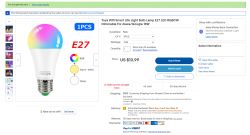
    LED WiFi RGBCW Tuya - teardown, BK7231N, programming with my Tasmota replacement
    RGBCW here means Red Green Blue Cool Warm, i.e. the available colors - red, green, blue, cold (white), warm (white).
    This 'light bulb' requires only access to our home WiFi and Tuya application - you do not need any hub or gate.
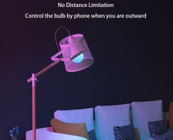
    LED WiFi RGBCW Tuya - teardown, BK7231N, programming with my Tasmota replacement
    LED WiFi RGBCW Tuya - teardown, BK7231N, programming with my Tasmota replacement
    In addition to the entire range of colors, the bulb offers Tuya automations (timers, scenarios, etc.) and various colorful animations, also following the rhythm of the music.
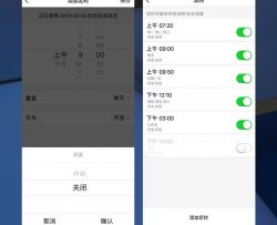
    LED WiFi RGBCW Tuya - teardown, BK7231N, programming with my Tasmota replacement
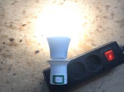
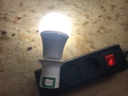
    Naturally, we also have control over its brightness:
    LED WiFi RGBCW Tuya - teardown, BK7231N, programming with my Tasmota replacement

    Test with the manufacturer's application
    First, I tested the bulb with the Tuya application, without changing the firmware.
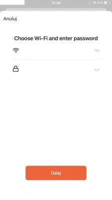
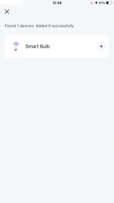
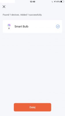
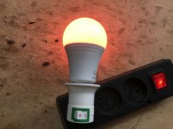
    Pairing is very easy. My iPhone detected the new device immediately, the light was blinking in pairing mode after first connected:
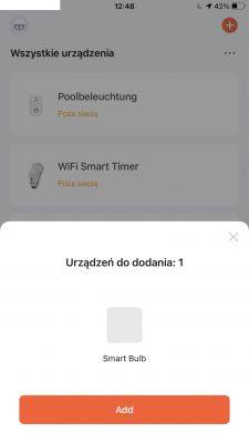
    LED WiFi RGBCW Tuya - teardown, BK7231N, programming with my Tasmota replacement LED WiFi RGBCW Tuya - teardown, BK7231N, programming with my Tasmota replacement LED WiFi RGBCW Tuya - teardown, BK7231N, programming with my Tasmota replacement LED WiFi RGBCW Tuya - teardown, BK7231N, programming with my Tasmota replacement LED WiFi RGBCW Tuya - teardown, BK7231N, programming with my Tasmota replacement LED WiFi RGBCW Tuya - teardown, BK7231N, programming with my Tasmota replacement
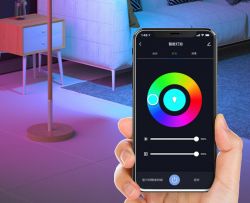
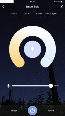
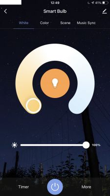
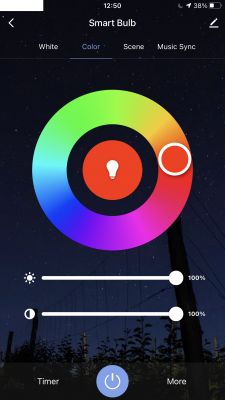
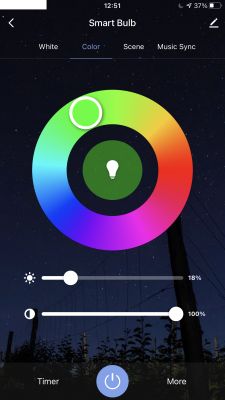
    No problems. This is what the color and brightness controls look like:
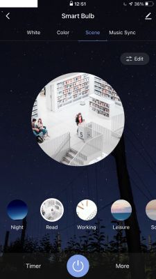
    LED WiFi RGBCW Tuya - teardown, BK7231N, programming with my Tasmota replacement LED WiFi RGBCW Tuya - teardown, BK7231N, programming with my Tasmota replacement
    LED WiFi RGBCW Tuya - teardown, BK7231N, programming with my Tasmota replacement LED WiFi RGBCW Tuya - teardown, BK7231N, programming with my Tasmota replacement LED WiFi RGBCW Tuya - teardown, BK7231N, programming with my Tasmota replacement
    LED WiFi RGBCW Tuya - teardown, BK7231N, programming with my Tasmota replacement LED WiFi RGBCW Tuya - teardown, BK7231N, programming with my Tasmota replacement
    The colors are expressive and bright. But you know, the Tuya application and its cloud do not interest us so much, so it's time to peek inside ...

    The interior of the bulb
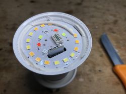
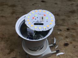
    Getting inside turned out to be very easy. I just managed to remove the plastic, milky dome with my bare hands, making a slight twisting motion.
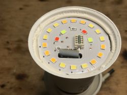
    LED WiFi RGBCW Tuya - teardown, BK7231N, programming with my Tasmota replacement LED WiFi RGBCW Tuya - teardown, BK7231N, programming with my Tasmota replacement
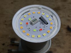
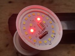
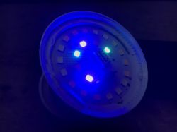
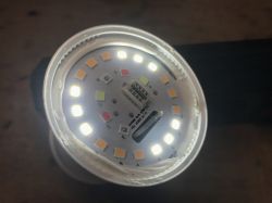
    Let's see when which LEDs are lit:
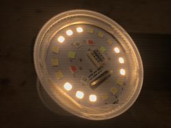
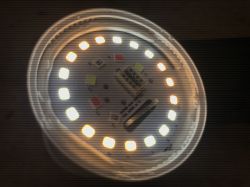
    LED WiFi RGBCW Tuya - teardown, BK7231N, programming with my Tasmota replacement LED WiFi RGBCW Tuya - teardown, BK7231N, programming with my Tasmota replacement LED WiFi RGBCW Tuya - teardown, BK7231N, programming with my Tasmota replacement LED WiFi RGBCW Tuya - teardown, BK7231N, programming with my Tasmota replacement LED WiFi RGBCW Tuya - teardown, BK7231N, programming with my Tasmota replacement
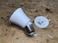
    The glue can be removed easily with a knife. It is enough to lift the PCB with LEDs. It is not bolted to the rest of the bulb base. I hope it won't heat up excessively, but it's only supposed to be 12W.
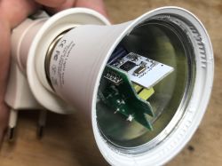
    LED WiFi RGBCW Tuya - teardown, BK7231N, programming with my Tasmota replacement LED WiFi RGBCW Tuya - teardown, BK7231N, programming with my Tasmota replacement LED WiFi RGBCW Tuya - teardown, BK7231N, programming with my Tasmota replacement
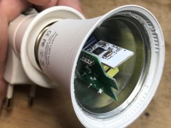
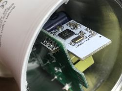
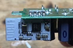
    The WiFi module inside is based on the BK7231N:
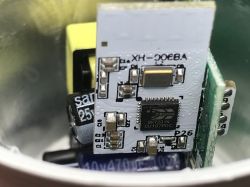
    LED WiFi RGBCW Tuya - teardown, BK7231N, programming with my Tasmota replacement LED WiFi RGBCW Tuya - teardown, BK7231N, programming with my Tasmota replacement LED WiFi RGBCW Tuya - teardown, BK7231N, programming with my Tasmota replacement
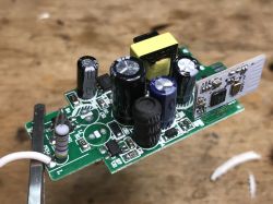
    It's time to get the whole module out. If we just want to program the BK7231N it may not be necessary if we can fit the soldering iron to its RX / TX pads. In any case, only one power cord is soldered, the other is only hooked onto the thread:
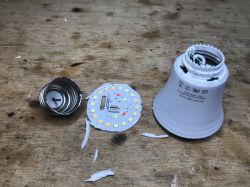
    LED WiFi RGBCW Tuya - teardown, BK7231N, programming with my Tasmota replacement LED WiFi RGBCW Tuya - teardown, BK7231N, programming with my Tasmota replacement
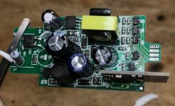
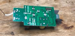
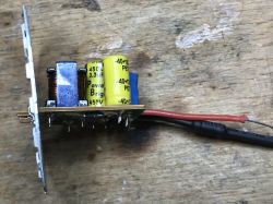
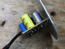
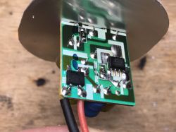
    Let's look at the electronics from inside:
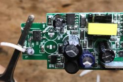
    LED WiFi RGBCW Tuya - teardown, BK7231N, programming with my Tasmota replacement LED WiFi RGBCW Tuya - teardown, BK7231N, programming with my Tasmota replacement LED WiFi RGBCW Tuya - teardown, BK7231N, programming with my Tasmota replacement LED WiFi RGBCW Tuya - teardown, BK7231N, programming with my Tasmota replacement LED WiFi RGBCW Tuya - teardown, BK7231N, programming with my Tasmota replacement
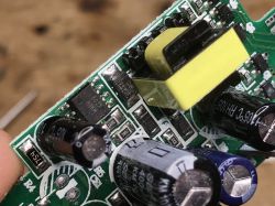
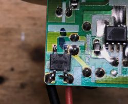
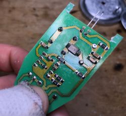
    At the input we have a fuse resistor (RF1 - Resistor Fusible 1?), A full bridge rectifierMB6S, then there are places for additional capacitors and a choke (creating a Pi filter?), In addition, there is one electrolytic capacitor for 400V and a controller for the 802X A0KH converter, which, more precisely, does not I analyzed, although I can see, among others there a 1R0 resistor (i.e. one ohm), on which the converter can measure the current (the shunt resistor). ES2JF is an ultrafast diode there, maybe from a snubber from the inverter? The F7 (FR107) diodes in the SOD-123 next to it are also fast. The element marked on the U2 board (the marking on the element is illegible) is probably the LDO regulator providing 3.3V for the WiFi module. Color switching transistors (there are five of them - one per channel R, G, B, W, C) are marked with N81Z, at the moment I have not found their catalog note ( if someone finds it, please comment ), but I must admit that in this topic I was more focused on the programming aspect of this 'light bulb', which will be discussed in a moment.
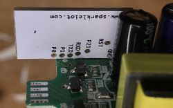
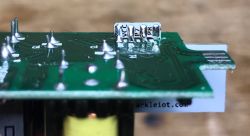
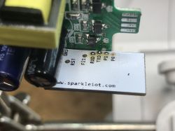
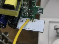
    The WiFi module itself is XH-0068A by sparkleiot com based on BK7231N:
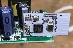
    LED WiFi RGBCW Tuya - teardown, BK7231N, programming with my Tasmota replacement LED WiFi RGBCW Tuya - teardown, BK7231N, programming with my Tasmota replacement LED WiFi RGBCW Tuya - teardown, BK7231N, programming with my Tasmota replacement LED WiFi RGBCW Tuya - teardown, BK7231N, programming with my Tasmota replacement
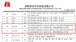
    The signals P0 and P1 as well as TXD and RXD are seen here. P0 and P1 is actually a UART too, but not for programming, but only a debug log output:
    LED WiFi RGBCW Tuya - teardown, BK7231N, programming with my Tasmota replacement
    However, only TXD and RXD will be useful for programming. Possibly also RST (but we can reset by cutting off the power).
    The photos also show what signals come from the WiFi module to the PCB - among others. P7, P8, P9, P6, P24. PWM pins...

    Programming of the BK7231N
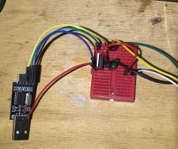
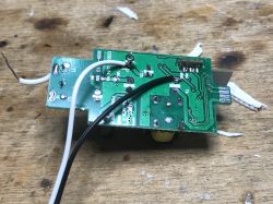
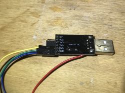
    To program the BK7231N, we need to connect an external power supply (disconnect the product from the mains, of course), preferably 3.3V via some own LDO (I used TC1264-3.3), because 5V would damage the WiFi module and connect the UART converter to the TX and RX pins of the BK7231N.
    Power connection:
    LED WiFi RGBCW Tuya - teardown, BK7231N, programming with my Tasmota replacement
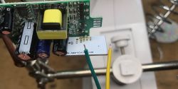
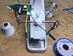
    RX and TX connection. Soldering can be tricky. I used flux and first added some solder on wires and pads, and then soldered wires to the pads:
    LED WiFi RGBCW Tuya - teardown, BK7231N, programming with my Tasmota replacement LED WiFi RGBCW Tuya - teardown, BK7231N, programming with my Tasmota replacement LED WiFi RGBCW Tuya - teardown, BK7231N, programming with my Tasmota replacement LED WiFi RGBCW Tuya - teardown, BK7231N, programming with my Tasmota replacement
    Power section and connection on the breadboard (3.3V connection is prepared in such a way so it's easy to disconnect it in order to force the system reboot).
    LED WiFi RGBCW Tuya - teardown, BK7231N, programming with my Tasmota replacement LED WiFi RGBCW Tuya - teardown, BK7231N, programming with my Tasmota replacement
    Only Python programmer works for BK7231N, BKwriter1.60 won't do it here.
    Download and install this tool:
    https://github.com/OpenBekenIOT/hid_download_py
    Prepare the firmware in the QIO version (not UA!), compile yourself or get it from here:
    https://github.com/openshwprojects/OpenBK7231T_App
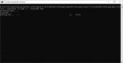
    Then use the command:
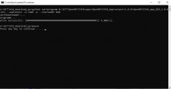
    python uartprogram W:\GIT\OpenBK7231N\apps\OpenBK7231N_App\output\1.0.0\OpenBK7231N_app_QIO_1.0.0.bin --unprotect -d com9 -w --startaddr 0x0
    First run the programmer with this command:
    LED WiFi RGBCW Tuya - teardown, BK7231N, programming with my Tasmota replacement
    At this stage, reboot (aka reset) the system (cut off and connect the power supply - sometimes it takes several times to get it; you can also reset with EN/RST pin):
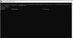
    LED WiFi RGBCW Tuya - teardown, BK7231N, programming with my Tasmota replacement
    LED WiFi RGBCW Tuya - teardown, BK7231N, programming with my Tasmota replacement
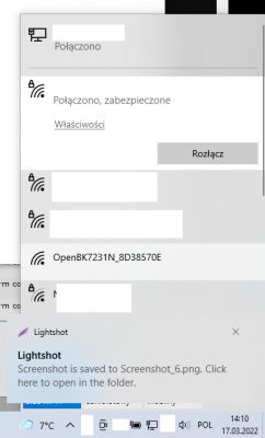
    Success. After restarting, you should see an open WiFi network for firmware configuration:
    LED WiFi RGBCW Tuya - teardown, BK7231N, programming with my Tasmota replacement
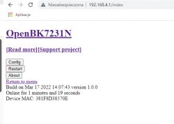
    Connect to it and enter the configuration page at 192.168.4.1.
    In case of any problems, if DHCP does not work, set your device IP manually to something like 192.168.4.15 (static IP), reconnect to WiFi and try again:
    LED WiFi RGBCW Tuya - teardown, BK7231N, programming with my Tasmota replacement
    The roles of the pins are easy to assign - you could already see what signals go to the PCB:
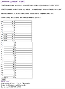
    LED WiFi RGBCW Tuya - teardown, BK7231N, programming with my Tasmota replacement
    NOTE: when setting channel indexes, keep order: 1 - red, 2 - green, 3 - blue, 4 - cool white, 5 - warm white
    This is the default order used by "color" command (for MQTT as well).
    Continue configuration (MQTT etc) like in these topics (they are both in Polish and English versions):
    Garden Tuya CCWFIO232PK Double Relay - BK7231T - Programming
    Qiachip Smart Switch - BK7231N / CB2S - interior, programming
    The RGBCW (color picker) interface itself is not fully ready yet.
    When it comes to setting the color in one go, there is a "color" command, which works in the same way as in Tasmota.
    Color command syntax:
    
    color #RRGGBB[CW][WW]
    

    The color is in hex format, successive bytes corresponds to successive channels. It is enough to properly format the query on the Home Assistant side and we can set all the colors at once.
    Example of a query that sets the color red:
    
    color #FF0000
    

    If we want to know what color is what code, we can find "RGB hex color picker" on the web.
    This command can also be sent via MQTT, for example from Home Assistant.

    Can such a bulb help you save electricity?
    Let's start with the basics. Standby power consumption with lights turned off. It should be noted here that if we have a normal light switch and we turn off the light in the room, of course this consumption also disappears, but it is always just a few pennies...
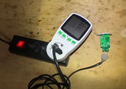
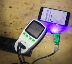
    LED WiFi RGBCW Tuya - teardown, BK7231N, programming with my Tasmota replacement
    Double-checking with the second meter:
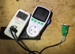
    LED WiFi RGBCW Tuya - teardown, BK7231N, programming with my Tasmota replacement
    Standby - 0.5W. Comparable with other smart products (eg Tuya, Blitzwolf sockets).
    Now the colors:
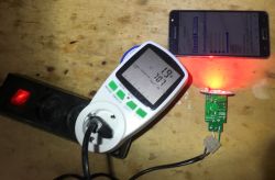
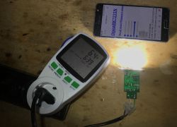
    LED WiFi RGBCW Tuya - teardown, BK7231N, programming with my Tasmota replacement
    LED WiFi RGBCW Tuya - teardown, BK7231N, programming with my Tasmota replacement LED WiFi RGBCW Tuya - teardown, BK7231N, programming with my Tasmota replacement
    And the most interesting - all the colors at once...
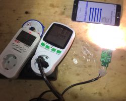
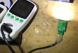
    LED WiFi RGBCW Tuya - teardown, BK7231N, programming with my Tasmota replacement
    The energy consumption (just over 6W) does not resemble the sum of the energy consumption of the individual channels. The main power supply seems to be limiting the current. So with this bulb we will never get more than 6W ...
    Dimming test:
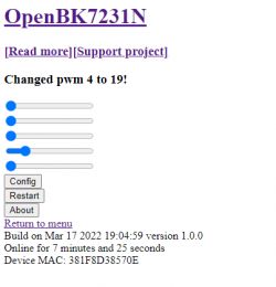
    LED WiFi RGBCW Tuya - teardown, BK7231N, programming with my Tasmota replacement
    LED WiFi RGBCW Tuya - teardown, BK7231N, programming with my Tasmota replacement
    Dimming works ok, very practical option. It allows, for example, to reduce the power consumption to just only 2W while maintaining a certain acceptable level of lighting in the room.


    For comparison - the inside of an ordinary LED bulb
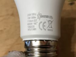
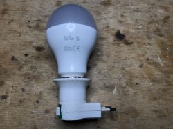
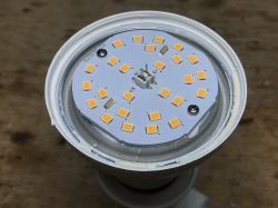
    First, the 13W bulb (nominal):
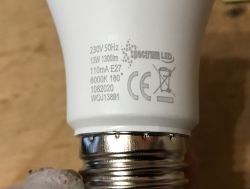
    LED WiFi RGBCW Tuya - teardown, BK7231N, programming with my Tasmota replacement
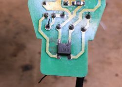
    Two burned LEDs, of course this can be fixed:
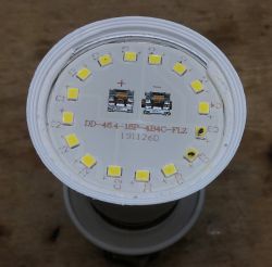
    LED WiFi RGBCW Tuya - teardown, BK7231N, programming with my Tasmota replacement
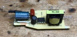
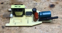
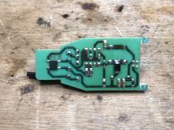
    Interior:
    LED WiFi RGBCW Tuya - teardown, BK7231N, programming with my Tasmota replacement LED WiFi RGBCW Tuya - teardown, BK7231N, programming with my Tasmota replacement
    LED WiFi RGBCW Tuya - teardown, BK7231N, programming with my Tasmota replacement LED WiFi RGBCW Tuya - teardown, BK7231N, programming with my Tasmota replacement
    LED WiFi RGBCW Tuya - teardown, BK7231N, programming with my Tasmota replacement LED WiFi RGBCW Tuya - teardown, BK7231N, programming with my Tasmota replacement
    LED WiFi RGBCW Tuya - teardown, BK7231N, programming with my Tasmota replacement
    MB10FH Bridge Rectifier, BP2861 Constant Current LED Controller:
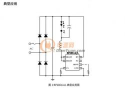
    LED WiFi RGBCW Tuya - teardown, BK7231N, programming with my Tasmota replacement
    Second, 14W:
    LED WiFi RGBCW Tuya - teardown, BK7231N, programming with my Tasmota replacement
    LED WiFi RGBCW Tuya - teardown, BK7231N, programming with my Tasmota replacement
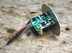
    PCB with LEDs screwed to the heat sink:
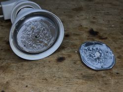
    LED WiFi RGBCW Tuya - teardown, BK7231N, programming with my Tasmota replacement LED WiFi RGBCW Tuya - teardown, BK7231N, programming with my Tasmota replacement
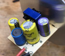
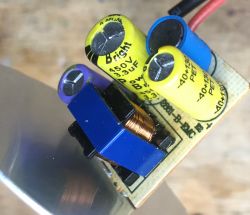
    Much better cooling, the entire housing dissipates heat here , the first one is probably 13W only written on the housing.
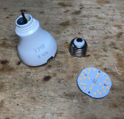
    LED WiFi RGBCW Tuya - teardown, BK7231N, programming with my Tasmota replacement
    LED WiFi RGBCW Tuya - teardown, BK7231N, programming with my Tasmota replacement LED WiFi RGBCW Tuya - teardown, BK7231N, programming with my Tasmota replacement
    LED WiFi RGBCW Tuya - teardown, BK7231N, programming with my Tasmota replacement LED WiFi RGBCW Tuya - teardown, BK7231N, programming with my Tasmota replacement
    LED WiFi RGBCW Tuya - teardown, BK7231N, programming with my Tasmota replacement
    Similar layout. BP2833D, surprisingly in THT.
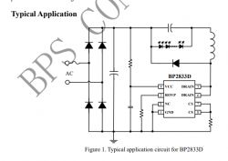
    LED WiFi RGBCW Tuya - teardown, BK7231N, programming with my Tasmota replacement

    Other ways to control RGBCW in Tuya bulbs
    Finally, I would like to mention that in some other Tuya bulbs RGBCW control is done via the I2C interface. On the board with LEDs there is a dedicated controller (already with integrated transistors) and the BK7231N (either T or another) communicates with it via I2C. I am also going to support such dimming in the future. An example of such a controller can be SM2135:
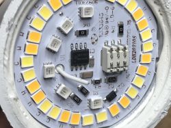
    LED WiFi RGBCW Tuya - teardown, BK7231N, programming with my Tasmota replacement
    This, however, will be on a different topic.

    Summary
    This Tuya Smart Bulb does not deliver promised 12W, but only 6W [/b] . More power will not be squeezed out of it, because it must be limited by the LED supply system, even when I force 100% duty on all channels (R, G, B, C, W) through my own firmware. However, this is not a surprise, with such poor cooling, probably the 12W would be an overkill.
    In standby it consumes 0.5W (because the WiFi module is still working), just like other products of this type (WiFi sockets, contacts, etc.).
    Besides, it's not that bad ... I can see some potential in such a bulb. The colors are unlikely to be useful in a practical way, but e.g. changing the temperature of the light (cold for work, warm for relaxation) is already a useful feature, and the possibility of dimming (e.g. as part of energy saving or late evening) is also something that could be used on a daily basis.
    There is BK7231N inside - my firmware supports it . It's a bit of a drag to access inside, but it is still possible to do this without destroying the casing.
    I know that I have not presented the full integration here (for example, my firmware is missing a convenient, graphical color picker), but I will try to develop it futher in the upcoming updates.
    Feel free to follow:
    https://github.com/openshwprojects/OpenBK7231T_App
    I wonder how long will this LED smart bulb last. Does any of the forum users use this type of smart bulbs, e.g. as an alternative to replacing light switches with the 'smart' ones, and share their experiences?
    I am attaching interesting doc about the BK7231.

    Cool? Ranking DIY
    Helpful post? Buy me a coffee.
    About Author
    p.kaczmarek2
    Moderator Smart Home
    Offline 
    p.kaczmarek2 wrote 11833 posts with rating 9930, helped 566 times. Been with us since 2014 year.
  • ADVERTISEMENT
  • #2 19939777
    ElectroTom
    Level 25  
    Thanks as always great.
  • ADVERTISEMENT
  • #3 19940087
    p.kaczmarek2
    Moderator Smart Home
    ElectroTom wrote:
    Thanks as always great.

    Thanks, it would seem that this is another BK7231N, and in fact I am just introducing basic corrections to the batch so that it can function at all ...

    For example, with the product from the topic, I realized that initially PWM did not work at all on the BK7231N platform, and in turn it still works on the BK7231T, although their operation in both cases was almost identical.

    Both of these chips are similar but have two different SDKs that are slightly different ...

    After a short error search, I discovered what was wrong.

    On the BK7231N platform, use bk_pwm_initialize to start the PWM module. Otherwise it doesn't work. On the BK7231T you don't have to call it, it's enough bk_pwm_start and bk_pwm_update_param . It's obvious that you need to initialize PWM, but the operation of this on the T platform baffled me.

    Of course, the fix is already in the repository so users don't have to do it themselves:
    https://github.com/openshwprojects/OpenBK7231...mmit/c8184264f04f4654e177005b3ed0593da8fcabea

    Well, it's a lot of fun to get it all into serviceable condition, and the next IoT device reviews are on the way ....

    There are also new reports in this thread:
    https://www.elektroda.com/rtvforum/topic3866123-300.html#19920755
    e.g. this bulb with I2C (post # 322).
    Helpful post? Buy me a coffee.
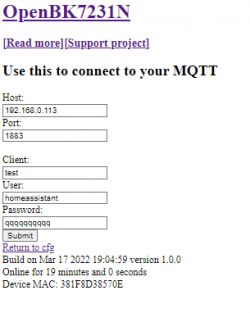
  • #4 19941395
    szeryf3
    Level 29  
    As always, an interesting and reliable description
  • ADVERTISEMENT
  • #5 19970646
    p.kaczmarek2
    Moderator Smart Home
    It's time for little update.
    I have prepared a new, better LED driver for compatibility with Home Assistant.
    Here is basic configuration description.

    First, I assume you have light configured and ready:
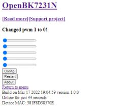
    LED WiFi RGBCW Tuya - teardown, BK7231N, programming with my Tasmota replacement
    Of course MQTT has to be set up at this point as well:
    LED WiFi RGBCW Tuya - teardown, BK7231N, programming with my Tasmota replacement
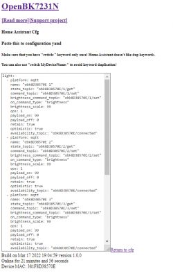
    Then go to "Generate Home Assistant Config", but do not copy whole config, you will have to modify it:
    LED WiFi RGBCW Tuya - teardown, BK7231N, programming with my Tasmota replacement
    Copy your device ID (eg. obk8D38570E) to this template:
    
      - platform: mqtt
        name: obk8D38570E
        rgb_command_template: "{{ '#%02x%02x%02x0000' | format(red, green, blue)}}"
        rgb_state_topic: "cmnd/obk8D38570E/led_basecolor_rgb"
        rgb_command_topic: "cmnd/obk8D38570E/led_basecolor_rgb"
        command_topic: "cmnd/obk8D38570E/led_enableAll"
        availability_topic: "obk8D38570E/connected"
        payload_on: 1
        payload_off: 0
        brightness_command_topic: "cmnd/obk8D38570E/led_dimmer"
        brightness_scale: 100
        brightness_value_template: "{{ value_json.Dimmer }}"
        color_temp_command_topic: "cmnd/obk8D38570E/led_temperature"
        color_temp_state_topic: "cmnd/obk8D38570E/ctr"
        color_temp_value_template: "{{ value_json.CT }}"
    

    Add this template to Home Assistant configuration.yaml and restart your HA.
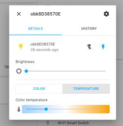
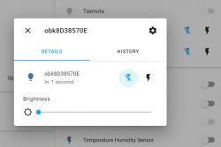
    You should get something like this:
    LED WiFi RGBCW Tuya - teardown, BK7231N, programming with my Tasmota replacement
    Click here to see hidden options:
    LED WiFi RGBCW Tuya - teardown, BK7231N, programming with my Tasmota replacement
    In color mode, you have a color picker. This is RGB only:
    LED WiFi RGBCW Tuya - teardown, BK7231N, programming with my Tasmota replacement
    In temperature mode, you get temperature slider:
    LED WiFi RGBCW Tuya - teardown, BK7231N, programming with my Tasmota replacement

    Some important notes:
    - on RGB picker, you choose only RGB values, no brightness. For brightness you have separate slider
    - brightness is remembered when toggling between RGB and temperature modes
    - disabling/enabling light does not reset your settings, so if you set color to red, and turn off and on bulb, the color is still red
    - this system behaves like one in Tuya, so there is a never a moment when all RGBCW LEDs are on. You can either have RGB leds on (at certain fractions), or CW leds on. Never all at once, just like in Tuya.
    - this system is not able to read back the value of light bulb right now (not really needed, as in general light bulbs don't have buttons to be pressed and Tuya also doesn't support it)
    If you want to see the source code, go here:
    https://github.com/openshwprojects/OpenBK7231T_App/blob/main/src/cmnds/newLEDDriver.c
    but better give me some time to tidy this up, it's a mess.
    Helpful post? Buy me a coffee.
  • ADVERTISEMENT
  • #6 19985789
    p.kaczmarek2
    Moderator Smart Home
    IMPORTANT UPDATE.
    There was a bug related to LED PWMs on BK7231T platform (BK7231N was not affected). It turned out that N version clamps PWM (so 110% duty cycle) is clamped to 100% and T just sets duty to 0 when invalid value is passed. It's now fixed in latest version of my firmware. Please update your bulbs.
    It seems that our forum user @ferbulous has experienced this issue at least once. It was also partially caused by invalid RGB scaling (also fixed).

    EXTRA WARNING:
    Please never try to set all R G B C W channels to 100% - the smart bulbs are not designed to work with all channels on. It's always either RGB or CW, never all ot once. It might reset your bulb or even maybe damage it. Do not risk it.
    Helpful post? Buy me a coffee.
  • #7 19987610
    ferbulous
    Level 18  
    @p.kaczmarek2 thanks for the new update
    I will try it soon once i get home

    Now that power monitoring is available, is it possible to add some sort of openbkt rules? On tasmota, i would add rule that turns off the relay once it reaches low power consumption. Useful as travel plugs

    As for mi bulb, those silicon are definitely annoying to remove just like the e27 bulb i’m testing now. Which makes tuya cloudcutter come in handy

    Also, is it possible for a port of openbkt to this chip?
    CKW04 by ewelink

    Woolley Smart Touch Switch WiFi Push Button Light Switch No Neutral Wire Required RF Remote Control Smart Home Automation Module
    https://a.aliexpress.com/_mOjBhGi

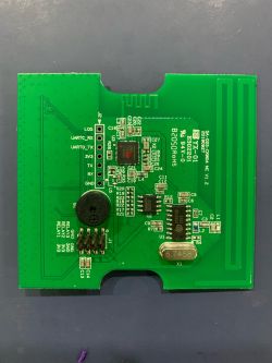
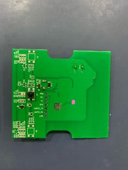
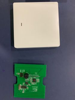
    LED WiFi RGBCW Tuya - teardown, BK7231N, programming with my Tasmota replacement LED WiFi RGBCW Tuya - teardown, BK7231N, programming with my Tasmota replacement LED WiFi RGBCW Tuya - teardown, BK7231N, programming with my Tasmota replacement
  • #8 19989618
    p.kaczmarek2
    Moderator Smart Home
    ferbulous wrote:

    Now that power monitoring is available, is it possible to add some sort of openbkt rules? On tasmota, i would add rule that turns off the relay once it reaches low power consumption. Useful as travel plugs


    Ok, since you're not the first person mentioning it, I've started adding simple events system for you. Can you describe more uses cases of Tasmota rules that you consider important and most often used?

    Right now, I am going to support:
    
    addChangeHandler Current above 100 setChannel 0 0
    

    Code above will disable relay when current from BL0942 (or similiar) is above 100mA

    
    setEventHandler OnClick 11 setChannel 1 0
    

    Code above will disable relay when button on pin 11 is clicked
    
    setEventHandler OnHold 11 addChannel 1 10 
    

    Code above will add 10% to PWM channel when button on pin 11 is held.

    But that's the initial draft, I can improve it, what are the requirements in your opinion?


    CKW04 ? I haven't seen any SDKs for that one yet
    Helpful post? Buy me a coffee.
  • #9 20044837
    p.kaczmarek2
    Moderator Smart Home
    IMPORTANT UPDATE
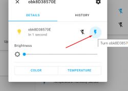
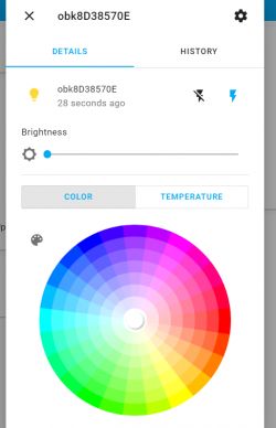
    I have updated led driver to broadcast received values by MQTT. My current configuration yaml:
    Code: YAML
    Log in, to see the code

    I have added support for rgb_state_topic with rgb_value_template, same for brightness_state_topic and color_temp_state_topic.
    Helpful post? Buy me a coffee.
Topic summary

The discussion revolves around flashing a Tuya smart LED bulb (12W, E27) with a Tasmota clone using the BK7231N chip. The user details a teardown process, USB to UART programming, and power consumption measurements. Key updates include fixes for PWM functionality on the BK7231N and improvements for compatibility with Home Assistant, including MQTT configuration for RGB and dimming features. Users are cautioned against setting all RGB channels to 100% simultaneously to avoid potential damage. Additional features and configurations for event handling and power monitoring are also discussed.
Summary generated by the language model.
ADVERTISEMENT