logo elektroda
logo elektroda
X
logo elektroda

[BK7231N - CBU-IPEX] Suraielec Smart Wi-Fi Low Voltage Transformer

mbetter 1356 4
ADVERTISEMENT
  • #1 20768595
    mbetter
    Level 5  

    I'm trying to flash this device (Amazon), but it's not working so far.

    I was able to write the QIO file with uartprogram, powering with 3.3V from a lab power supply. The write says it was successful, but subsequent reads fail with CRC error. On inspection, I see that I'm able to read out the binary from flash correctly, except that it's truncated: it's missing 69488 bytes at the end. Any clues as to what this means?

    Furthermore, the device shows no signs of life after flashing (no access point).
  • ADVERTISEMENT
  • #2 20768652
    p.kaczmarek2
    Moderator Smart Home
    Hello, have you tried removing the shielding to confirm that's really BK7231N?
    Helpful post? Buy me a coffee.
  • ADVERTISEMENT
  • #3 20769032
    mbetter
    Level 5  

    No, I just went by the datasheet. Should I just try flashing as 7231T?
  • ADVERTISEMENT
  • #4 20772013
    mbetter
    Level 5  

    Ok, I tried again and was successful flashing with the GUI flasher. (Either I did something wrong, or the device didn't want to boot up when connected to 3.3V from a lab power supply after flashing. But it started fine when I plugged it into mains again.) Detailed description to follow.

    Added after 32 [minutes]:
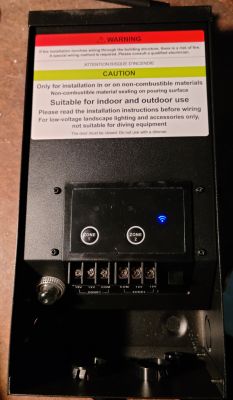
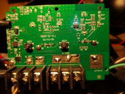
    Low-voltage transformer housing with warning panel and control buttons. Main board of a Wi-Fi transformer with visible connectors and electronic components. Close-up of a motherboard with soldered wires and visible components.

    It's easy to open the case and access the mainboard, taking care not to damage the antenna cable that runs from the antenna at the top of the enclosure. It can be disconnected by prying it off.

    To flash, I soldered wires to the module's pin 14 (3V3), 15 (TX1), 16 (RX1), and GND by soldering a header pin to one of the unpopulated through-holes at KEY3. I could also have soldered pin 18 (CEN) for good measure since it's needed for flashing, but ended up just touching a wire to the pad.

    The SoC pins are connected as follows:
    P6 WiFi LED (inverted)
    P7 Zone 1 button
    P8 Zone 2 button
    P24 Zone 1 relay and LED
    P26 Zone 2 relay and LED


    And the config:
    
    {
      "vendor": "Suraielec",
      "bDetailed": "0",
      "name": "Low Voltage 200W Smart Wi-Fi Transformer",
      "model": "ULTW20B",
      "chip": "BK7231N",
      "board": "N/A",
      "flags": "0",
      "keywords": [
        "landscape",
        "transformer",
        "led"
      ],
      "pins": {
        "6": "WifiLED_n;3",
        "7": "Btn;1",
        "8": "Btn;2",
        "24": "Rel;1",
        "26": "Rel;2"
      },
      "command": "",
      "image": "https://obrazki.elektroda.pl/2257367400_1697425459.jpg",
      "wiki": "https://www.elektroda.com/rtvforum/viewtopic.php?p=20772013"
    }
    

  • #5 20772084
    p.kaczmarek2
    Moderator Smart Home
    Well, if flashing worked in N mode, then T will not work anyway, because N mode sends a flash unlock packet that is not handled by T. Anyway, that's not imporant anymore since I can see you managed to get it running. Good job!

    This device have many more accessible pins, it seems you could easily use them to extend the functionality, add DHT11 or anything.

    Thanks for the template, I will add it now.
    Helpful post? Buy me a coffee.
ADVERTISEMENT