logo elektroda
logo elektroda
X
logo elektroda

[BK7231N][CBU] ZMAi-90 Smart Energy Meter Teardown and Flashing

thebeardeddragon 7674 74
ADVERTISEMENT
  • #1 20815631
    thebeardeddragon
    Level 4  
    Hi all!

    Some time ago I acquired a ZMAi-90 smart energy meter to control energy consumption for a bunch of servers.
    This is a common device for Tasmota flashers: Link

    Since the beginning, I wanted to take control of the device locally from my LAN, removing cloud services completely. I actually found a few posts from around 2019 where people managed to flash Tasmota into them, when they used the ESP8266 chip. Thus, I decided to purchase a new one to try and flash it.

    For my surprise, these devices had been updated, and now come by default with a CBU using the BK7231N chip.

    Upon digging on the internet, I came by the OpenBeken project, which will literally save my life since this is now the only way to make these devices cloud-free without needing to resolder a new chip.

    I have all the tools, will provide quality pictures, and got 3 of these devices ready to break if needed just to get them fully working; but I do need some guidance, given that my experience with flashing and electronics is quite short and the information for every specific device seems to be very different.

    This guy did an incredible job of reverse-engineering all the connections between the WiFi board and the actual relay, to the point where even Tasmota included a patch to allow the mapping of the pins of this device. Thus, I was hopping some of the information he published in these posts will be useful, once the device is flashed, to facilitate the configuration:
    Part 1: Link
    Part 2: Link
    Part 3: Link

    Now, let's look at some pictures.
    The device from outside - a quite simple single-phase smart meter:
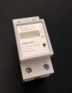
    Front view of the ZMAi-90 smart energy meter.

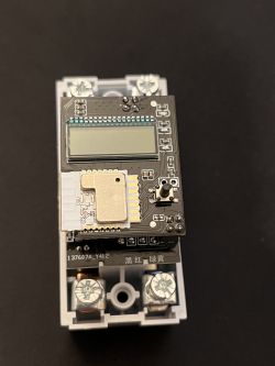
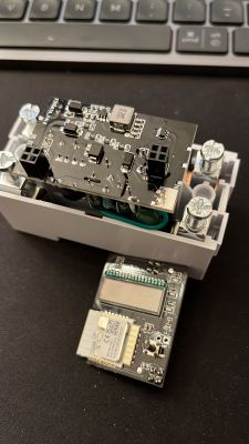
    Let's open it up:
    Top view of an open smart energy meter with visible circuit board.
    Open interior of a smart energy meter showing the relay board and other components.
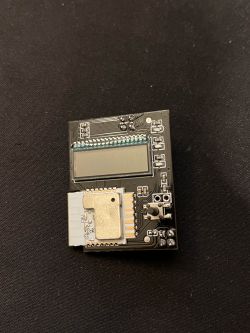
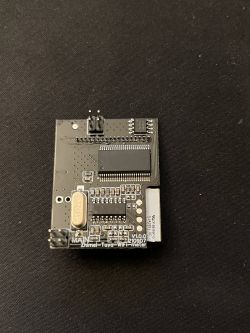
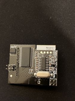
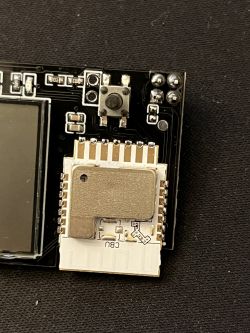
    Circuit board with electronic components on a dark background Printed circuit board of the ZMAi-90 smart energy meter on a black background. Circuit board inside the ZMAi-90 smart energy meter. Image of an electronic module with a visible button and CBU marking.

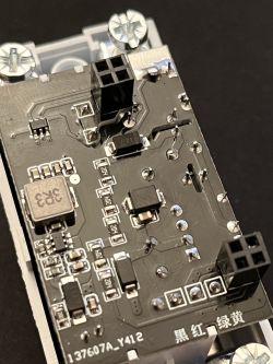
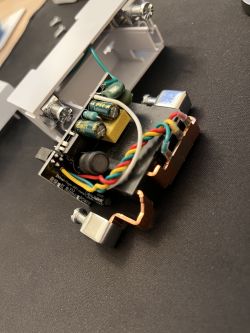
    The second board with the relay:
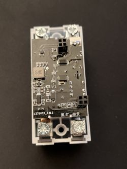
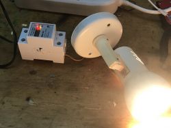
    Interior view of the ZMAi-90 energy meter showing the circuit board. Close-up of the circuit board of a smart energy meter with BK7231N chip. Image of the interior of the ZMAi-90 smart energy meter with visible electronic components.

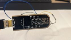
    And my flashing device with high precision grapples. I've also got a Raspberry that I can use for flashing:
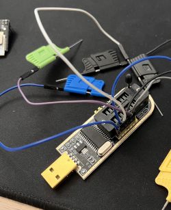
    Programmer connected to a circuit using precision grabbers

    So, laid out the problem, my sources, and the resources at my disposition... where to start?! I'd like this to turn out useful for the whole community so that we can publish a complete procedure on how to do this step by step.

    Many thanks in advance!

    P.D.: I'm also aware of this other post about CBU Link, but honestly it's extremely messy and difficult to follow, plus the device in that post uses different pins. Is there any info from that post applicable to my case?
  • ADVERTISEMENT
  • Helpful post
    #2 20815719
    p.kaczmarek2
    Moderator Smart Home
    Welcome to Elektroda,
    the first step would be to determine whether your Zmai-90 is a TuyaMCU version or not. As far as I know, there are both ZMAI devices that are using TuyaMCU with UART communication between MCU and WIFI module, and ZMAI devices that are using some different control chip.
    If that's a TuyaMCU version, are the dpIDs of packets already known? If not, we have an analyzer for that: https://github.com/openshwprojects/TuyaMCUAnalyzer
    So, where is UART port (TX1/RX1) of CBU connected? Does it connect to the MCU? Are you able to take a 2MB flash dump from that device for analysis?
    Helpful post? Buy me a coffee.
  • #3 20818389
    thebeardeddragon
    Level 4  

    Thanks for the prompt reply!

    p.kaczmarek2 wrote:

    the first step would be to determine whether your Zmai-90 is a TuyaMCU version or not....
    If that's a TuyaMCU version, are the dpIDs of packets already known?


    In the link I provided there are some numbers listed that seem to be dpIDs. Could you confirm?
    https://templates.blakadder.com/ZMAi-90.html


    p.kaczmarek2 wrote:

    So, where is UART port (TX1/RX1) of CBU connected? Does it connect to the MCU?


    Never done this before, but I guessed what you were asking could be achieved by running a 3.3V through a small speaker and see which points of the board closed the circuit (and made the speaker beep) with pins TX1/RX1. If this assumption is correct, my findings are as follows:
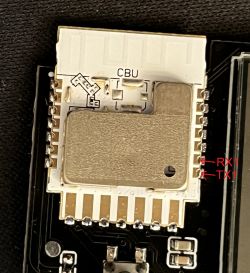
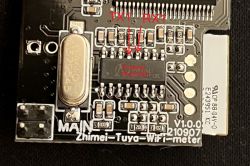
    These are the TX1/RX1 pins:
    Close-up of a circuit board with RX1 and TX1 pins marked.

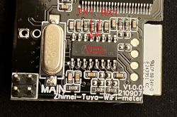
    They connect to these pins on the RN8209C chip
    Close-up of a PCB with the RN8209C chip and marked TX1 and RX1 pins.

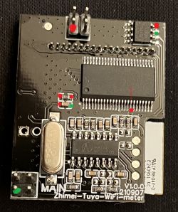
    Other points where I have observed connectivity with both RX1 and TX1 pins on the RN8209C chip. Red is strong connection, green is weak (maybe resistor in path):
    Image of a circuit board with an RN8209C chip and red and green dots indicating connection points.


    p.kaczmarek2 wrote:

    Are you able to take a 2MB flash dump from that device for analysis?


    Given this new information, could you confirm where I need to solder/attach the cables to perform the dump? Will it work if I attach the cables to the pins on the RN8209C chip?

    Thanks.
  • #4 20821160
    thebeardeddragon
    Level 4  

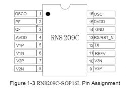
    I am a bit confused on how to take a 2MB flash dump from the RN8209C chip, since its pins don't align with the typical distribution of other chips I've used before like BIOS ones. Any tips for this?

    Pin assignment diagram for RN8209C chip in SOP16L package
  • Helpful post
    #5 20821174
    p.kaczmarek2
    Moderator Smart Home
    Flash dump should be taken from the WiFi module, so we can restore to Tuya firmware in case that something goes wrong. We do not flash the MCU itself. OpenBeken should be able to communicate with the MCU if TuyaMCU is used. If not, we can try to implement the required protocol...

    CBU is very similiar to CB3S/CB2S, you can look on our channel for CB2S tutorials: https://www.youtube.com/@elektrodacom
    Helpful post? Buy me a coffee.
  • ADVERTISEMENT
  • #6 20821299
    thebeardeddragon
    Level 4  

    Ah! Sorry, I thought you asked me to provide a dump of the RN chip, not the CBU. I will work on getting the dump from the CBU.

    A different question, in order to use the TuyaMCU analyzer to identify the dpIDs, how do I get the hex packet dump? Do I need to intercept communication between the CBU and the MCU?

    Thanks.
  • ADVERTISEMENT
  • Helpful post
    #7 20821311
    p.kaczmarek2
    Moderator Smart Home
    There are multiple ways to handle it. One would be to capture the hex data itself and use our analyzer:
    https://github.com/openshwprojects/TuyaMCUAnalyzer
    the problem is that you must never connect your USB to UART converter to devices powered from mains, you should use an optoisolator for that and I am not sure if you know well how to handle that kind of process. Working with mains can be very dangerous.

    Alternatively, you could try to get dpIDs from Tuya itself. I don't know the exact process, but as far as I know, you can also just create a Tuya developer account for free, pair your device with Tuya and look up there the datapoints published by this device. There might be someone else here who knows more about it, I don't know, @ferbulous , maybe? That would be a safer approach.
    Here is something that might help, altough it's for Zigbee, but it should be the same for WiFi:
    https://www.zigbee2mqtt.io/advanced/support-n..._tuya_data_points.html#_7-display-device-logs
    Related: https://community.home-assistant.io/t/localtu...-local-keys-but-also-dp-data-point-ids/423236

    The last option (and worst option) would be guessing. You know, if device is powered by 230V, and sends something like 2300, we can fairly easy guess that's a voltage (multiplied by 10)... but still, I'd suggest you to try the second option first. The one with Tuya site.

    I think that you can also read similiar topics on our forum, for example:
    OpenBK7231T (WB3S) Config for Hiking DDS238-2 Smart Meter: Tasmota Guide & Teardown
    Helpful post? Buy me a coffee.
  • #8 20827013
    thebeardeddragon
    Level 4  

    Alright, I have fried the first chip. The screen stopped printing any information after a lot of power resets when I was trying to dump the contents of the flash. For some reason, I couldn't get any signal whatsoever from the TX1/RX1 pins on the CBU... Tried with different baud rates, different COM ports, different devices (USB-UART device and Arduino One).

    I wonder if I had broken the chip prior to this testing, thus not getting any comms.

    I will keep trying with the next device... Got 2 more available to fry!
  • #9 20827030
    p.kaczmarek2
    Moderator Smart Home
    You should never connect such device to PC when it's also connected to mains! This is very dangerous. The power supply may not be isolated. Please take extreme caution. You can only probe UART if you have used isolator module.
    Helpful post? Buy me a coffee.
  • #10 20827036
    thebeardeddragon
    Level 4  
    Thanks for the warning, but I didn't connect the mains! I only was doing the power reset by disconnecting the 3.3V cable and reconnecting.

    Just to be clear, I was only doing this on the CBU unit's PCB separately, detached from the relay and other components.
  • #11 20827052
    p.kaczmarek2
    Moderator Smart Home
    Are you sure that you're doing the process correctly? What is your setup for reading 2MB flash of the device? Are you using our flash tool? https://github.com/openshwprojects/BK7231GUIFlashTool

    Please do not confuse our flash tool (BK7231tool) that is used to read 2MB dump of BK7231 and later to flash OpenBeken to it with our Tuya protocol analyzer which is used to capture and decode TuyaMCU communication with the WIFI module
    Helpful post? Buy me a coffee.
  • #12 20827063
    thebeardeddragon
    Level 4  
    I was using bk_writer1.60 and following the instructions on this video: Link

    Nonetheless, I wasn't using the same USB-UART device as in the video, but a CH341A programmer. CBU TX1 pin attached to USB-UART RX, CBU RX1 pin to USB-UART TX, and GND + 3.3V. That's it.

    Didn't detect anything when clicking "read", and then tried to use the TX/RX pins on an Arduino to read raw bits, but the CBU did not emit a single bit through the TX pins.
  • #13 20827069
    p.kaczmarek2
    Moderator Smart Home
    bkWriter 1.60 may not work good for N platform (BK7231N), it works okay for BK7231T.
    Try hid_download_py approach or try our new flasher.
    https://github.com/openshwprojects/BK7231GUIFlashTool


    Are you following the flashing procedure correctly?
    1. click read
    2. disconnect power
    3. reconnect power so it can "get bus" and begin reading

    Alternatively, you can try to alter point 2:
    2. Disconnect 3.3V from power supply to Beken, then take VDD wire from Beken side and short it to GND, then disconnect it from GND, and connect it back to power supply (this ensures that BK resets itself, just make sure to do not confuse the wires, do not short the power supply to ground)
    Helpful post? Buy me a coffee.
  • #14 20827103
    thebeardeddragon
    Level 4  

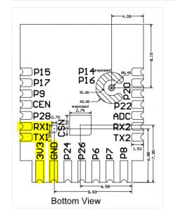
    Yes, I was following that procedure exactly. Using the following pins:

    Bottom view diagram of an electronic module with highlighted pins 3V3, RX1, and GND.

    Segment of a table with information about pins: GND, 3V3, TX1, RX1.


    There are also these other pins that I didn't try:

    Screenshot of a table describing RX2 and TX2 pins and their functions.


    I will try the new software next.
  • ADVERTISEMENT
  • #15 20827152
    p.kaczmarek2
    Moderator Smart Home
    TX2 is only for debug log output. TX1/RX1 is for both flashing and TuyaMCU
    Helpful post? Buy me a coffee.
  • #16 20827174
    thebeardeddragon
    Level 4  

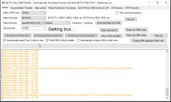
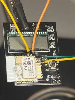
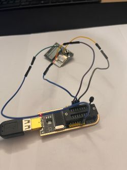
    No luck. I tried both on/off and shorting CEN.

    Screenshot of BK7231 Easy UART Flasher software with error messages at the bottom.

    Close-up of a PCB with yellow, orange, and green wires connected. Electronic circuit with a PCB connected to a USB adapter. CH341A programmer with visible pin labels on a black PCB.

    Is it possible that the other chip on the board is preventing communication on TX1?
  • #17 20827352
    p.kaczmarek2
    Moderator Smart Home
    Is the other chip still on the same board? Do they connect via UART1, namely RX1 and TX1?

    It is very often the case that the other chip connected via UART blocks the programming. I had to cut the traces or desolder the chip many times just to get the flashing to work. You should check now with multimeter whether RX1/TX1 is still connected somewhere on that board.
    Helpful post? Buy me a coffee.
  • #18 20827690
    thebeardeddragon
    Level 4  

    Yes, it is. As I explained in my previous posts, the energy-meter chip (RN8209C) is on the same board as the BCU. The BCU TX1/RX1 connect here:

    Close-up of a circuit board with RN8209C chip and TX1, RX1 markings.

    Is it possible to disable that chip without desoldering? This post made it work in a similar device like this:

    Instructions on using the serial cable for temporary soldering of pins.
  • #19 20827721
    p.kaczmarek2
    Moderator Smart Home
    It should be possible to put that chip in the RESET state, but you need to consult the datasheet for that. I usually go the "desoldering" or "cutting trace" route, because it's more universal.
    Helpful post? Buy me a coffee.
  • #20 20827737
    thebeardeddragon
    Level 4  

    I have tried putting it in reset mode using the technical sheet, by shorting the RST pin to GND. Still no communication detected on the RX1/TX1... Not a single bit.

    I am stuck and don't know how to proceed. Any advice?

    Also, if I ship this item to you, would you be able to do some research on it and publish the results?

    Thanks.
  • #21 20827764
    p.kaczmarek2
    Moderator Smart Home
    I can do that and I do that often for users on thi sforum, but I still have some devices in queue, so there might be a slight delay. Futhermore, the results strongly depend on the protocol used in the device itself. If that's TuyaMCU, then it will be very easy to support, one hour of work or so, but if it's somehow using a custom protocol, it can take much more time.
    Helpful post? Buy me a coffee.
  • #22 20838678
    p.kaczmarek2
    Moderator Smart Home
    Package from OP arrived so I am trying to investigate this device.

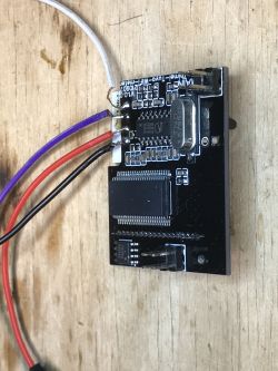
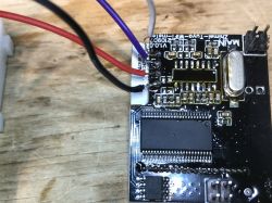
    There is GND, RX, TX and VDD on the pads:
    Photo of an electronic module with several connected wires.
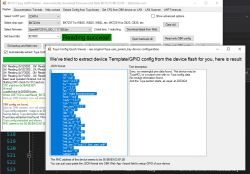
    I can read flash BUT ONLY by using a trick - short VDD from the WiFI module side to GND and then leave it floating, it will still read:
    Screenshot of BK7231 Easy UART Flasher tool showing successful data reading.
    Code: JSON
    Log in, to see the code

    I can't flash with my trick, and I can't reset the RN8209C because it's RST is on RX... to flash, you need to desolder RN8209C:
    PCB board with visible electronic components and connected wires.

    2MB backup attached.
    Helpful post? Buy me a coffee.
  • #23 20838775
    p.kaczmarek2
    Moderator Smart Home
    P6 (PWM0) is a WiFiLED

    Added after 7 [minutes]:

    P26 (PWM5) is Tipped LED

    Added after 2 [minutes]:

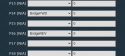
    there is a bridge relay somewhere, I heard it click when I randomly toggled pins, it requies two gpios

    Added after 2 [minutes]:

    P16 is one of bridge relay pins

    Added after 2 [minutes]:

    P14-P16 is a bridge relay pair

    Added after 1 [minutes]:

    yes, relay works:
    Screenshot showing GPIO pin settings on a device.

    Added after 8 [minutes]:

    P7 is PAIR button on the device
    Helpful post? Buy me a coffee.
  • #24 20838910
    thebeardeddragon
    Level 4  

    Thanks for being so quick!

    So, was I doing it wrong by using the TX1/RX1 pins on the other side of the board, or is it the same as the pins you used?

    Also, funny that you need to unsolder the RN chip... is there no way around this?

    As a final question, I see you figured out a few LED connections and the relay function, but what about the power metering (total power consumed and current W)? Is that going to work with OpenBK, or not?

    Cheers.
  • #25 20838936
    p.kaczmarek2
    Moderator Smart Home
    thebeardeddragon wrote:

    So, was I doing it wrong by using the TX1/RX1 pins on the other side of the board, or is it the same as the pins you used?

    The RX1/TX1 on the other side of the board are the same that are on CBU.
    I used a so-called "trick" or "hack" to read flash, I connected GND, TX, RX VDD to my USB to UART converter and 3.3V LDO, and on flash tool I started read flash, and then I shorted WiFi module VDD to GND to force-discharge capacitors and then I left VDD floating, but it still has read flash, it's the same thing that EEVBlog shown here:
    EEVblog #831 - Power A Micro With No Power Pin!
    I did it because it allowed WiFi module to power but left MCU unpowered. Otherwise MCU would interfere with flashing.

    Still, don't try that, it failed for OBK write anyway, most likely because flash write requires more current


    thebeardeddragon wrote:

    Also, funny that you need to unsolder the RN chip... is there no way around this?

    I had to desolder RN because it's connected via UART to WiFi module. As said above, I managed to trick-read flash without it, but I was not able to write new firmware that way.
    RN has to be desoldered because it RST_N is on RX anyway, so you can't put that in RESET state without blocking UART, sorry.


    thebeardeddragon wrote:

    As a final question, I see you figured out a few LED connections and the relay function, but what about the power metering (total power consumed and current W)? Is that going to work with OpenBK, or not?

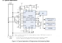
    I am afraid it's going to take some time, here's how this device made:
    Schematic of RN8209 single-phase energy measurement application.
    I will investigate PCB now to determine the connections, but it seems a custom driver will be needed for the LCD and power meter.
    Helpful post? Buy me a coffee.
  • #26 20839055
    thebeardeddragon
    Level 4  

    Great, thanks for your effort. It sounds like good progress.

    I wouldn't be too concerned about a firmware for the LCD screen, but power metering is quite important.

    This device sends a total number to Tuya Cloud, that starts at 0 when you first configure it, and then increases by 1 per each 0.1 kWh.

    For example, 230 kWh total consumption will be sent as "2300".

    So, if you can see the chip sending a reading like this, maybe you can export it.
  • #27 20839061
    p.kaczmarek2
    Moderator Smart Home
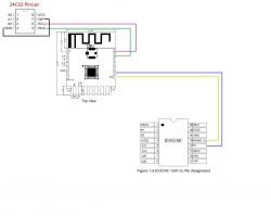
    Here is a draft of the most important connections:
    Connection diagram between 24C02, CBU, and RN8209C circuits.
    I will try to support the power meter, but it will require writing a driver from scratch.
    Helpful post? Buy me a coffee.
  • #28 20840241
    p.kaczmarek2
    Moderator Smart Home
    GPIOs as template:
    Code: JSON
    Log in, to see the code


    Added after 2 [hours] 11 [minutes]:

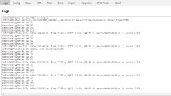
    Trying to communicate with RN...
    Screenshot of smart home application logs.
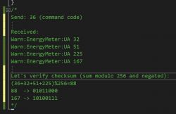
    Verification:
    Console with error messages and checksum calculation
    checksum matches!

    Added after 2 [hours] 29 [minutes]:

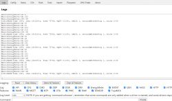
    @thebeardeddragon ok I implemented read operation with CRC:
    Screenshot of an IoT device management application log panel, showing various warning and informational messages.
    Helpful post? Buy me a coffee.
  • #29 20842263
    p.kaczmarek2
    Moderator Smart Home
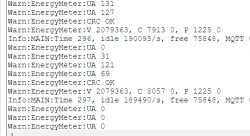
    Without load:
    Screenshot showing log data from an energy meter test.
    With 60W bulb:
    Screenshot of energy meter test results.
    Test setup:
    Electrical energy tester connected to a glowing light bulb on a wooden table.
    Helpful post? Buy me a coffee.
  • #30 20850811
    p.kaczmarek2
    Moderator Smart Home
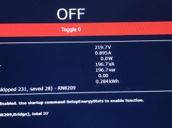
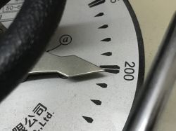
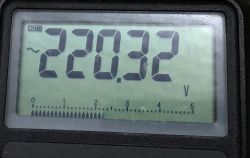
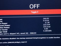
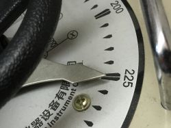
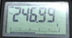
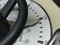
    Autotransformer test, 220V:
    Screen displaying parameters of an autotransformer test with voltage at 219.7 V. Close-up of an autotransformer gauge indicating voltage at 200V. Display of a meter showing a voltage reading of 220.32 V.
    247V:
    Display showing autotransformer test results with voltage and power values. The needle on an autotransformer gauge showing a voltage reading around 225V. Multimeter display showing a voltage of 246.99 V.
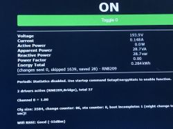
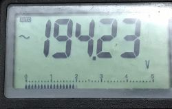
    194V:
    Display showing electrical parameters during autotransformer test. Close-up of an autotransformer meter gauge showing a reading of 175V. Multimeter display showing a voltage of 194.23 V.
    Helpful post? Buy me a coffee.

Topic summary

The discussion revolves around the ZMAi-90 smart energy meter, which utilizes the BK7231N chip and has been modified from earlier versions that used the ESP8266. Users are seeking to flash the device with OpenBeken firmware to eliminate reliance on cloud services. Initial steps involve determining if the device is a TuyaMCU version and identifying the UART connections for flashing. Several users share their experiences with flashing, including challenges with communication and the need to desolder components like the RN8209C chip to facilitate the process. The conversation also touches on the power metering functionality and the integration of the device with Home Assistant, highlighting issues with current measurements and the need for calibration. Users discuss various methods for reading flash memory and the importance of ensuring proper connections to avoid damaging the device.
Summary generated by the language model.
ADVERTISEMENT