Hello,
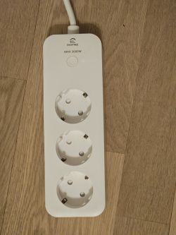
Teardown of Eightree Smart WiFi Power Strip with 3 AC Ports, 16A.
Bought on Amazon in December 2024, ASIN: B0C6X3YWTZ.
It has 3 independent AC slots and energy consumption monitoring.
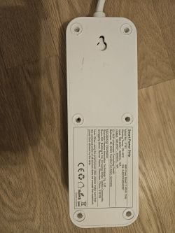
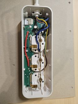
To open the device, remove the white pads and the 6 tri-angle (TA) screws.
Pictures
Flashing
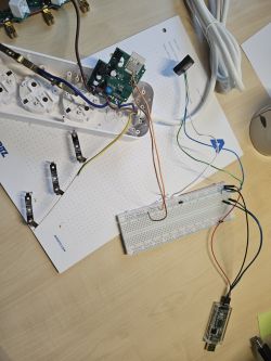
Was able to flash using a USB to Serial Adapter and BK7231GUIFlashTool.
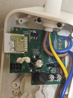
The schema from here seems correct:https://docs.libretiny.eu/boards/cbu
I tried it without soldering using this flashing jig (https://www.printables.com/model/763948-tuya-cbu-flashing-jig) but was not successful.
Soldering VCC and GND and for RX, TX and CEN holding it with the flashing jig worked. Reboot by connecting CEN (PIN18) to GND.
Config
extracted template
Original Firmware Backup
Teardown of Eightree Smart WiFi Power Strip with 3 AC Ports, 16A.
Bought on Amazon in December 2024, ASIN: B0C6X3YWTZ.
It has 3 independent AC slots and energy consumption monitoring.
To open the device, remove the white pads and the 6 tri-angle (TA) screws.
Pictures


Flashing
Was able to flash using a USB to Serial Adapter and BK7231GUIFlashTool.
The schema from here seems correct:https://docs.libretiny.eu/boards/cbu
I tried it without soldering using this flashing jig (https://www.printables.com/model/763948-tuya-cbu-flashing-jig) but was not successful.
Soldering VCC and GND and for RX, TX and CEN holding it with the flashing jig worked. Reboot by connecting CEN (PIN18) to GND.
Config
extracted template
{
   "sel_pin_pin":"20",
   "rl1_lv":"1",
   "bt_type":"0",
   "bt1_pin":"8",
   "rl3_pin":"26",
   "rl3_lv":"1",
   "net_trig":"2",
   "jv":"1.0.6",
   "netled1_lv":"0",
   "netled_reuse":"1",
   "total_bt_pin":"17",
   "vi_pin":"16",
   "total_stat":"2",
   "resistor":"1",
   "over_cur":"17000",
   "bt3_lv":"0",
   "bt1_lv":"0",
   "reset_t":"3",
   "netled1_pin":"9",
   "chip_type":"0",
   "rl2_lv":"1",
   "lose_vol":"75",
   "over_vol":"275",
   "module":"CBU",
   "bt3_pin":"24",
   "ele_pin":"14",
   "ch_cddpid1":"9",
   "rl2_pin":"7",
   "bt2_pin":"6",
   "ch_cddpid2":"10",
   "ch_cddpid3":"11",
   "total_bt_lv":"0",
   "ch_num":"3",
   "ele_fun_en":"1",
   "bt2_lv":"0",
   "rl1_pin":"22",
   "ch_dpid3":"3",
   "vol_def":"0",
   "ch_dpid1":"1",
   "sel_pin_lv":"1",
   "ch_dpid2":"2",
   "crc":"119"
}
Device configuration, as extracted from Tuya:
- BL0937 SEL on P20
- Button (channel 1) on P8
- Relay (channel 3) on P26
- Pair/Toggle All Button on P17
- BL0937 VI on P16
- WiFi LED on P9
- Button (channel 3) on P24
- BL0937 ELE on P14
- Relay (channel 2) on P7
- Button (channel 2) on P6
- Relay (channel 1) on P22
Device seems to be using CBU module, which is using BK7231N.
And the Tuya section starts, as usual, at 2023424
Original Firmware Backup


