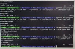
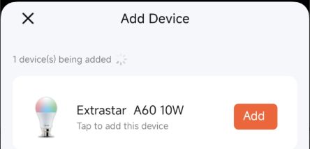
Hello, I'm back with an another smart bulb and this time it's a BK7231T-based device (The module inside is a WB3L). And... yes this one also came from a flea market
The branding on it states it's a ExtraStar A60WIFI-2, the 2 is probably because they come in a package of two.
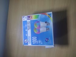
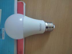
It's basically the same as the Kanlux S A60, I'm guessing they ship these under many brands.
Since I had previous experience with a W600-based lamp, this was a piece of cake in comparison to figure out.
Ok, so first things first, in order to proceed we will need:
- A soldering iron
- A UART-to-USB adapter (Logic level MUST be set to 3v3), this includes having the supply of 3.3V as well
- Some solder
- Tweezers, a small pair of pliers, scalpel and a flat-head screwdriver (For destructive opening of the device)
- Steady hands
- And some small insulated wires (preferably AWG30 because that's what I used)
Opening this device WILL damage the exterior housing so it's kinda an irreversible process sadly.
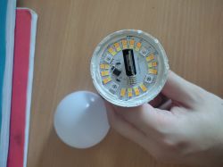
1) Start by prying at the contact between the plastic lens and the housing, I recommend trying to cut the silicone using a scalpel then using a large flat-heat screwdriver to pry the top housing open.
Once you succeed, you'll be met with this.
2) The inner LED ring can be removed, but it's quite a tricky process. It involves you going around the perimeter of the board trying to slice and remove as much of that white silicone as you can.
3) After you've removed a decent chunk of said silicone, use a pair of tweezers or mini pliers and try to pull out the board. You can also try prying with the screwdriver. But be VERY careful, you can rip the LED diodes straight off or damage any of the on-board components.
If you succeed, you'll be met with the following:
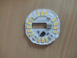
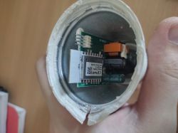
We don't actually need the white board for anything, we just want to get to the microcontroller, which is the TD-WB3L unit seen in the second picture.
We still don't have clear access to the board to do our soldering job, in order to completely remove it we still need to remove some other bits. The thing preventing us from just removing the board are the live and neutral wires located on the bottom of the unit.
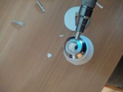
4) Removing the tip of the Edison plug.
This tip holds the live wire and can be released by just prying at the tip using a flat-head screwdriver and jamming it between the plastic and the tip like so:
5) Doing the same for the plug itself. I'd recommend prying at the part that has the pressed metal stamps against the housing of the lamp (the little metal dots)
This will release the the neutral wire, however be aware that the plug is held on tight and you can possibly damage it, so I'd advise to be extra careful during this part of the procedure.
Once you're successful, you'll be met with this:
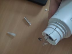
6) You should now be able to easily slide out the board for further soldering and then flashing of the device.
Pulling it out from the front, you'll get the following:
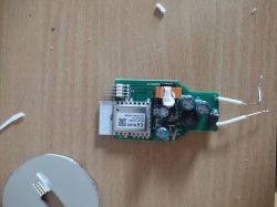
Following the datasheet I found about the board on the FCC's website, I've determined the following pins should be soldered to:
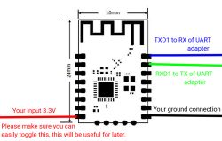
The 3.3V toggle is quite important because it's EXTREMELY hard to enter the bootloader if you don't have the toggle present. The time this device spends in the bootloader is very small, so you'll have to be fast. For just that I recommend having the switch. This can even be a wire you can easily disconnect/connect, like you'll see in a moment.
Take your time and solder these connection in whatever way you find most comfortable, but I find using tiny wires and a small tip extra helpful when making such small connections.
Once done, you'll be met with something akin to this:
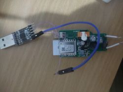
The blue jumper wire there is for me just to be able to easily toggle the power.
7) Flashing the thing
DISCLAIMER: As I'm a Linux user, I prefer to do things with the command line but you're free to use other methods. This method I'm demonstrating is my own experience, so I'm going to retell that:
7.1) Install bk7231tools
This should be available through your package manager, if it's not, then unfortunately this is the part you'll be on your own.
7.2) Back up the original firmware.
This is a contingency measure, not really necessary, but I like to do it in order to prevent mistakes from being permanent.
Now, before running a command, you want to remove power to the board. This is that switch I'm talking about. But be ready to plug it in once you execute it
(Change the USB serial adapter name obviously)
Annnd.... PLUG IT IN RIGHT AWAY. If you're lucky it will succeed the first try. If not, try a bunch of times until you get it right.
7.3) Two is one and one is none
Make sure you do multiple backups because doing just one may lead to a corrupted backup which you definitely don't want to have.
So again, but this time change the filename:
Same rules apply.
7.4) Make sure the backups are the same.
This way we can be sure that our backup job was valid:
This should NOT result in extra output being emitted. If it does, we have a problem.
7.5) My dumb solution for this problem
Anyway since I was personally not able to get a clean backup like until my 50th try, I did the following:
Made my own tool for comparing backups and creating a proper one
7.5.1) To enter this rabbit hole, compile the thing first
7.5.2) Make 3 or more backups
This is just to ensure that we have enough backups so that the wrong parts can be filtered out. (2 good backups win against 1 bad one, right?)
7.5.3) Merge them into one good one
This will generate a new file called backup.bin that should be your good one.
If that program crashes, you still have issues backing up. I'm sorry about that
7.6) Downloading the firmware
Assuming you actually got a good backup, lets proceed.
Get the firmware from this link
Find the one that corresponds to our setup. That would be BK7231T, the UART flash kind (.bin extension).
7.7) Flashing said firmware
Be VERY careful when flashing because this chip can be permanently bricked, so we need to add an offset to skip (the -s parameter) the bootloader section of the firmware, which is a sort-of fallback if the flashing operation were to fail.
Using the same setup as the backup(s), execute the following:
Change UART device name and flashing file as needed.
Once you're done, YOU DID IT
Now all that's left is to assemble and configure the device.
8) Test the device. Remove power after flashing and plug it in again, it should appear as a new Wi-Fi access point. Connect to it and go to 192.168.4.1.
Does it load? Great, we have a functional unit.
Before configuring, however I'd like to continue with the assembly.
9) Remove power
10) De-solder all the wires we just put in because we don't want any stray shorts.
11) Place the board back in the housing making sure that the two power wires go where they need to go.
12) Placing the tip and the plug back where they need to go.
There's a slightly confusing detail about the live wire being actually shorter than the neutral one, so when putting the plug back onto the housing, make sure to straighten the live wire so it actually goes through the hole for the pin on the plug.
13) Make sure that when putting the plug and pin back in that both the wires are touching what they need to touch in order to make electrical contact with their respective contacts but then don't short (obviously)
14) Don't forget to put the LED board back on, keeping in mind where the headers actually are and connecting them appropriately
15) Put the cap back on.
Since you've might've bent the housing a bit too much, like I did, you can use electrical tape around the perimeter of the housing and the cap to hold it on.
Ok, so the setup:
16) Screw the bulb onto the socket and turn the power on
17) Connect to the wireless network and open the website at 192.168.4.1
From here the procedure is the same as the Kanlux, but essentially go to:
18) Navigate to Configuration > Pin Assignment
19) And from there configure the following pins (the exact same as the Kanlux):
20) Click Save and return to the Home page.
From there you'll be able to configure the lamps color and temperature.
I'm sure you'll figure out the rest
Have a wonderful day
Also for that one guy who asks, here's the backup of my original firmware.
The branding on it states it's a ExtraStar A60WIFI-2, the 2 is probably because they come in a package of two.


It's basically the same as the Kanlux S A60, I'm guessing they ship these under many brands.
Since I had previous experience with a W600-based lamp, this was a piece of cake in comparison to figure out.
Ok, so first things first, in order to proceed we will need:
- A soldering iron
- A UART-to-USB adapter (Logic level MUST be set to 3v3), this includes having the supply of 3.3V as well
- Some solder
- Tweezers, a small pair of pliers, scalpel and a flat-head screwdriver (For destructive opening of the device)
- Steady hands
- And some small insulated wires (preferably AWG30 because that's what I used)
Opening this device WILL damage the exterior housing so it's kinda an irreversible process sadly.
1) Start by prying at the contact between the plastic lens and the housing, I recommend trying to cut the silicone using a scalpel then using a large flat-heat screwdriver to pry the top housing open.
Once you succeed, you'll be met with this.

2) The inner LED ring can be removed, but it's quite a tricky process. It involves you going around the perimeter of the board trying to slice and remove as much of that white silicone as you can.
3) After you've removed a decent chunk of said silicone, use a pair of tweezers or mini pliers and try to pull out the board. You can also try prying with the screwdriver. But be VERY careful, you can rip the LED diodes straight off or damage any of the on-board components.
If you succeed, you'll be met with the following:


We don't actually need the white board for anything, we just want to get to the microcontroller, which is the TD-WB3L unit seen in the second picture.
We still don't have clear access to the board to do our soldering job, in order to completely remove it we still need to remove some other bits. The thing preventing us from just removing the board are the live and neutral wires located on the bottom of the unit.
4) Removing the tip of the Edison plug.
This tip holds the live wire and can be released by just prying at the tip using a flat-head screwdriver and jamming it between the plastic and the tip like so:

5) Doing the same for the plug itself. I'd recommend prying at the part that has the pressed metal stamps against the housing of the lamp (the little metal dots)
This will release the the neutral wire, however be aware that the plug is held on tight and you can possibly damage it, so I'd advise to be extra careful during this part of the procedure.
Once you're successful, you'll be met with this:

6) You should now be able to easily slide out the board for further soldering and then flashing of the device.
Pulling it out from the front, you'll get the following:

Following the datasheet I found about the board on the FCC's website, I've determined the following pins should be soldered to:

The 3.3V toggle is quite important because it's EXTREMELY hard to enter the bootloader if you don't have the toggle present. The time this device spends in the bootloader is very small, so you'll have to be fast. For just that I recommend having the switch. This can even be a wire you can easily disconnect/connect, like you'll see in a moment.
Take your time and solder these connection in whatever way you find most comfortable, but I find using tiny wires and a small tip extra helpful when making such small connections.
Once done, you'll be met with something akin to this:

The blue jumper wire there is for me just to be able to easily toggle the power.
7) Flashing the thing
DISCLAIMER: As I'm a Linux user, I prefer to do things with the command line but you're free to use other methods. This method I'm demonstrating is my own experience, so I'm going to retell that:
7.1) Install bk7231tools
This should be available through your package manager, if it's not, then unfortunately this is the part you'll be on your own.
7.2) Back up the original firmware.
This is a contingency measure, not really necessary, but I like to do it in order to prevent mistakes from being permanent.
Now, before running a command, you want to remove power to the board. This is that switch I'm talking about. But be ready to plug it in once you execute it
Code: Bash
(Change the USB serial adapter name obviously)
Annnd.... PLUG IT IN RIGHT AWAY. If you're lucky it will succeed the first try. If not, try a bunch of times until you get it right.
7.3) Two is one and one is none
Make sure you do multiple backups because doing just one may lead to a corrupted backup which you definitely don't want to have.
So again, but this time change the filename:
Code: Bash
Same rules apply.
7.4) Make sure the backups are the same.
This way we can be sure that our backup job was valid:
Code: Bash
This should NOT result in extra output being emitted. If it does, we have a problem.
7.5) My dumb solution for this problem
Anyway since I was personally not able to get a clean backup like until my 50th try, I did the following:
Made my own tool for comparing backups and creating a proper one
7.5.1) To enter this rabbit hole, compile the thing first
Code: Bash
7.5.2) Make 3 or more backups
This is just to ensure that we have enough backups so that the wrong parts can be filtered out. (2 good backups win against 1 bad one, right?)
7.5.3) Merge them into one good one
Code: Bash
This will generate a new file called backup.bin that should be your good one.
If that program crashes, you still have issues backing up. I'm sorry about that
7.6) Downloading the firmware
Assuming you actually got a good backup, lets proceed.
Get the firmware from this link
Find the one that corresponds to our setup. That would be BK7231T, the UART flash kind (.bin extension).
7.7) Flashing said firmware
Be VERY careful when flashing because this chip can be permanently bricked, so we need to add an offset to skip (the -s parameter) the bootloader section of the firmware, which is a sort-of fallback if the flashing operation were to fail.
Using the same setup as the backup(s), execute the following:
Code: Bash
Change UART device name and flashing file as needed.
Once you're done, YOU DID IT
Now all that's left is to assemble and configure the device.
8) Test the device. Remove power after flashing and plug it in again, it should appear as a new Wi-Fi access point. Connect to it and go to 192.168.4.1.
Does it load? Great, we have a functional unit.
Before configuring, however I'd like to continue with the assembly.
9) Remove power
10) De-solder all the wires we just put in because we don't want any stray shorts.
11) Place the board back in the housing making sure that the two power wires go where they need to go.
12) Placing the tip and the plug back where they need to go.
There's a slightly confusing detail about the live wire being actually shorter than the neutral one, so when putting the plug back onto the housing, make sure to straighten the live wire so it actually goes through the hole for the pin on the plug.
13) Make sure that when putting the plug and pin back in that both the wires are touching what they need to touch in order to make electrical contact with their respective contacts but then don't short (obviously)
14) Don't forget to put the LED board back on, keeping in mind where the headers actually are and connecting them appropriately
15) Put the cap back on.
Since you've might've bent the housing a bit too much, like I did, you can use electrical tape around the perimeter of the housing and the cap to hold it on.
Ok, so the setup:
16) Screw the bulb onto the socket and turn the power on
17) Connect to the wireless network and open the website at 192.168.4.1
From here the procedure is the same as the Kanlux, but essentially go to:
18) Navigate to Configuration > Pin Assignment
19) And from there configure the following pins (the exact same as the Kanlux):
| Pin name | Funciton | Index | P6 | PWM | 4 | P7 | PWM | 3 | P8 | PWM | 0 | P24 | PWM | 1 | P26 | PWM | 2 |
20) Click Save and return to the Home page.
From there you'll be able to configure the lamps color and temperature.
I'm sure you'll figure out the rest
Have a wonderful day
Also for that one guy who asks, here's the backup of my original firmware.
Cool? Ranking DIY


