logo elektroda
logo elektroda
X
logo elektroda

[BK7231/CB2S] Ceiling Fan Controller with Dimmer and RF Remote - Assistance Configuring

totallylost 1593 7
ADVERTISEMENT
  • #1 20821830
    totallylost
    Level 2  
    Hi all. I am new to elektroda and also Tasmota configuration. Please forgive me if I have overlooked some key tutorial topic(s).

    I purchased a Tuya compatible Ceiling Fan Remote Control Kit with light dimmer and RF remote hoping to get it running Local Only on HomeAssistant. I feel like I may have bitten off more than I can chew on this project and am wondering if people have any tips on configuring this device?

    Manufacturer: San Sheng (Zhongshan), but it is branded [or unbranded] under various names.
    Model: RE-028W, SS-T28
    Chipset: CB2S
    Replacement: ESP8685-WROOM-03
    Notes: The unit connects electrically to load and neutral without a ground.

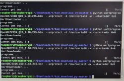
    I did successfully flash the CB2S to OpenBeken, but after failing to get any results with attempts to configure, I attempted to hook up my dusty old Oscilloscope [which I don't have much experience with] and as soon as I contacted the probe's ground to the CB2S GND pin something popped and the fan unit just kept clicking [I presume b/c the fan unit isn't grounded]. After removing the CB2S chip the unit operated just fine using the included RF remote. At this point I managed to load up Tasmota 4MB onto an ESP8685-WROOM-03 and soldered it onto the board.

    Chip Connections to the Board:
    On the front of the chip, only CEN was soldered to the board.
    On the back of the chip, all pins were soldered to the board.

    ESP8685 seems to be a direct drop-in replacement just with different pin names.
    CB2S : CEN || 3v3 | GND | RX1 | TX1 | P24 | P26
    ESP-x : _EN || 3V3 | GND | RX_ | TX_ | IO5 | IO4

    My current understanding is on the ESP I need to configure Pins GPIO20 / GPIO21 (RX / TX) and GPIO5 / GPIO4 but do not know what to configure them as or what function each pin performs.

    I've attempted to play with normal settings such as PWM, LED, and Relay and have had no success commanding a change to a light-bulb or hearing the fan-speed relays activating nor seen the config web-app updating with changes performed by the RF remote.
    Sometimes PWM on one of the pins gives me a brightness slider and toggle switch in the Tasmota web-app, but has no effect in real life.
    I don't understand the PWM channel config yet, and the app seems to warn against using them unless an advanced user. At some point my RF remote stopped working and needed re-synchronized to the unit. I'm convinced it was due to some PWM channel I tested, so maybe my actions did something....


    I've tried configuring GPIO20/21 as Serial RX/TX and TuyaMCU RX/TX, but have not observed any differences nor know if RX/TX need swapped if these are even the right settings.

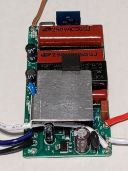
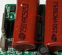
    Something else to note: On my Feit light switch I noticed a clearly emblazoned TuyaMCU chip... with this Fan controller I have not observed any such chip. The only chips that in my uneducated opinion look like they have any smarts appear unlabeled and/or under a capacitor and unable to clearly view (I still think it's unlabeled from what I can observe).

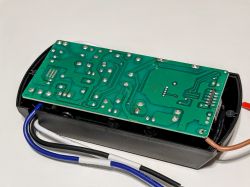
    Below are some images that might be of use to someone more familiar with electronics. Let me know if you have any questions or need better photos of the board to assist with recommendations. I appreciate any assistance provided.
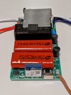
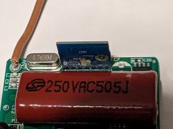
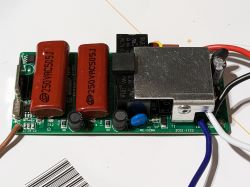
    PCB with electronic components, including a CB2S module and two large capacitors.
    Close-up of a circuit board with electronic components. Circuit board of a ceiling fan remote control showing capacitors and components. Electronic module for ceiling fan control. Printed circuit board inside a device casing with protruding wires.
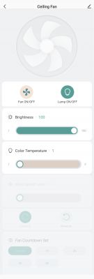
    App screen for controlling a ceiling fan and light dimmer remotely.
  • ADVERTISEMENT
  • #2 20822003
    p.kaczmarek2
    Moderator Smart Home
    Let's start with TuyaMCU config extraction. Do you still have that CB2S around, even with OBK installed? Follow this guide:
    https://www.youtube.com/watch?v=WunlqIMAdgw&ab_channel=Elektrodacom
    And attach here extracted file or at least the extracted JSON data.

    Isn't TuyaMCU there?
    Electronic circuit board with two large capacitors labeled 250VAC505J.

    Quote:

    I contacted the probe's ground to the CB2S GND pin something popped and the fan unit just kept clicking [I presume b/c the fan unit isn't grounded].

    This is a mistake and might do a short circuit because that kind of devices usually don't have isolated power supplies.

    Quote:

    Sometimes PWM on one of the pins gives me a brightness slider and toggle switch in the Tasmota web-app, but has no effect in real life.

    I'd still think that's a TuyaMCU device.
    On Tasmota, I'd try:
    https://templates.blakadder.com/treatlife_DS03.html
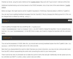
    Screenshot of instructions for configuring TuyaMCU in Tasmota.
    If you do the part from the screenshot and press buttons on remote, do you get those messages in Tasmota?

    Do you know dpIDs of this device?
    Helpful post? Buy me a coffee.
  • ADVERTISEMENT
  • #3 20841004
    totallylost
    Level 2  
    My apologies, I was expecting an email notification on replies, but was away anyway for holiday. Thank you for the quick response.

    -I have attached the original BK7231 Flasher read binary.

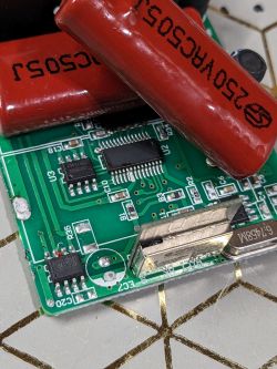
    -I did just desolder that capacitor and one of the chips is actually unlabeled. (See attached photo)

    -On the currently installed ESP8685-WROOM-03 w/Tasmota, SetOption97 did not provide valid heartbeats using either =0 nor =1. Both resulted in the "TYA: Send 55..." outputs
    -I do not know the DpIDs. I presume I could know this if I can get the Option97 comms working.


    -The CB2S got zapped when I tried to hookup to the O-scope. I did buy another of this product, but was hoping to keep it mint until I figure out what exactly needs to happen in case I can't get this working.
    **Is it possible TuyaMCU got zapped at the same time causing invalid heartbeats in the console?

    -It is possible I wiped a valid OBK before fully testing the flashed device. If I recall correctly, I clicked something OBK related after flashing the CB2S. I do not recall if it was in the Flasher or in the OpenBeken web GUI.
    **On that note: if I only flash the OpenBeken firmware onto a fresh CB2S, should it already have the necessary configuration that it needs?


    -There were other potential issues during the BK7231 configuration Read suggesting it was not able to correctly parse the OBK. (Details below, but REDACTED some details in case it is sensitive information)


    "Basic read operation finished, but now it's time to verify...
    Starting CRC check for 512 sectors, starting at offset 00
    CRC matches 0x8433208A!
    All read!
    Loaded total 0x200000 bytes
    Wrote 2097152 to readResult_BK7231N_QIO_CeilingFanRemote_SS-T28_115200_linked_2023-15-11-20-10-46.bin
    Backup 2MB created, now will attempt to extract OBK config.
    It's not an OBK config, header is bad
    OBK config not found.
    Backup 2MB created, now will attempt to extract Tuya config.
    Tuya config extractor - magic is at 2023424
    Saving debug Tuya decryption data to lastRawDecryptedStrings.bin
    Malformed key?             [repeated 18 times]
    Tuya keys extraction has found 74 keys
    Tuya config extracted and shown."


    Code: JSON
    Log in, to see the code


    Sorry. That was a lot of information. I hope it makes sense.

    Close-up of a circuit board with various electronic components, including large red capacitors and an unidentified chip.
  • ADVERTISEMENT
  • #4 20841161
    p.kaczmarek2
    Moderator Smart Home
    This is TuyaMCU device. You need to configure it by creating autoexec.bat . We can't automatically extract dpIDs yet, only the baud rate . You can try to just guess them after running TuyaMCU driver in OBK, but it's always better to either capture them with Tuya firmware or find them on Tuya developer site.
    Here are sample autoexecs:
    https://github.com/openshwprojects/OpenBK7231T_App/blob/main/docs/autoexecExamples.md
    Here are OBK commands:
    In OBK, once you init TuyaMCU with a proper baud, you can use tuyaMcu_sendQueryState command to request TuyaMCU state from the MCU.

    What is currently soldered in that device, ESP or BK7231?
    Helpful post? Buy me a coffee.
  • #5 20842375
    totallylost
    Level 2  

    Thanks for the response.
    I currently have an ESP8266-WROOM-03 with Tasmota installed.

    Based on the information you provided, I was able to map out all of the critical dpIDs and values to functions and then successfully issue TuyaSend commands via the console to change their states.

    dpIDs retrieved from my Tuya Cloud Project.
    {"20":"Lamp ON/OFF","22":"Brightness","23":"Color Temperature","60":"Fan ON/OFF","62":"Wind Speed Level","63":"Direction Fan","101":"Fan Countdown Set"}


    I have questions regarding the Autoexec.bat and configuration.
    Since I was able to activate functions via console, it seems the only GPIO configuration needed is GPIO20 (TuyaRx) and GPIO21 (TuyaTx) on the ESP32.
    What is the correlation of Channels to dpID? The autoexec examples seem to be 1:1
    Are all of my commands on Channel 0, or should the dpID number be the Channel number?

    Example:
    04:36:49.567 {"TuyaReceived":{"Data":"55AA030700083E0200040000000358","Cmnd":7,"CmndData":"3E02000400000003","DpType2Id62":3,"62":{"DpId":62,"DpIdType":2,"DpIdData":"00000003"}}}
    04:36:49.570 TYA: fnId=0 is set for dpId=62
    04:36:49.871 {"TuyaReceived":{"Data":"55AA03070005650400010078","Cmnd":7,"CmndData":"6504000100","DpType4Id101":0,"101":{"DpId":101,"DpIdType":4,"DpIdData":"00"}}}
    04:36:49.875 TYA: fnId=0 is set for dpId=101


    I'll be doing a lot more research this weekend to see how much further I can get with preparing a configuration script. I am completely new to Tasmota and OpenBK.
  • ADVERTISEMENT
  • Helpful post
    #6 20842512
    p.kaczmarek2
    Moderator Smart Home
    Autoexec.bat is used in OpenBeken firmware.
    dpIDs are only used by TuyaMCU.
    channels are used in OBK.
    The way to map dpID to channel is the following command:
    
    linkTuyaMCUOutputToChannel	[dpId] [varType] [channelID] [bDPCache-Optional]
    

    This command acts like a bridge between a dpID and a channel. It provides a two-way synchronization, so it supports both updating via TuyaMCU (eg. user presses physical button) and via WiFi module (user clicks button on OBK panel).
    Here are our docs:
    https://github.com/openshwprojects/OpenBK7231T_App/blob/main/docs/commands.md
    See more autoexec examples at:
    https://github.com/openshwprojects/OpenBK7231T_App/blob/main/docs/autoexecExamples.md
    Helpful post? Buy me a coffee.
  • #7 20843943
    totallylost
    Level 2  

    Awesome breakdown.
    I discovered that although similar in appearance, OBK and Tasmota aren't that similar. I ended up flashing my second unit with OpenBeken and everything seems to be working in the Web GUI using the autoexec.bat.

    Since there are no pins used and it is only DpId to Channel mappings in the autoexec, how can I integrate that into an OBK template? Would it be empty and a user need to visit the Documentation linked in the template to know that the autoexec needs to be uploaded to the device?

    Also, what is the intent of "flags": "1024" in the JSON template?

    ...Now I need to remember how to configure my HA with MQTT and generate some.
  • #8 20845545
    p.kaczmarek2
    Moderator Smart Home
    totallylost wrote:

    Awesome breakdown.
    I discovered that although similar in appearance, OBK and Tasmota aren't that similar. I ended up flashing my second unit with OpenBeken and everything seems to be working in the Web GUI using the autoexec.bat.

    TuyaMCU mapping is different because our approach is more flexible and scriptable. That being said, most of the commands are still similiar, and we have the same JSON format, we are even compatible with Tasmota Control App:


    And with Tasmota Device Groups:


    totallylost wrote:

    Since there are no pins used and it is only DpId to Channel mappings in the autoexec, how can I integrate that into an OBK template? Would it be empty and a user need to visit the Documentation linked in the template to know that the autoexec needs to be uploaded to the device?

    You are correct, we sadly don't have a field for that yet, currently you have to copy. Do you have any idea how to handle it better?

    totallylost wrote:

    Also, what is the intent of "flags": "1024" in the JSON template?

    There are our flags definitions: https://github.com/openshwprojects/OpenBK7231T_App/blob/main/docs/flags.md

    totallylost wrote:

    ...Now I need to remember how to configure my HA with MQTT and generate some.

    This may work:


    Helpful post? Buy me a coffee.

Topic summary

The discussion revolves around configuring a Tuya-compatible Ceiling Fan Remote Control Kit with light dimmer and RF remote for local operation on HomeAssistant. The user successfully flashed the CB2S chipset to OpenBeken but faced challenges in configuration, including issues with TuyaMCU communication and invalid heartbeats. Participants provided guidance on extracting dpIDs, using autoexec.bat for OpenBeken, and mapping dpIDs to channels. The user managed to retrieve dpIDs and issue commands via the console, leading to successful integration with the web GUI. Further inquiries were made regarding OBK templates and the intent of specific JSON flags.
Summary generated by the language model.
ADVERTISEMENT