Elektroda.com
Elektroda.com
X

OpenBeken and TuyaMCU dimmer - configuration guide/tutorial

p.kaczmarek2 13431 66
This content has been translated flag-pl » flag-en View the original version here.
  • OpenBeken and TuyaMCU dimmer - configuration guide/tutorial
    Here I will show how you can easily use a TuyaMCU device (dimmer) with my OpenBeken and connect it to Home Assistant . OpenBeken is an alternative, open source software for IoT devices, offering, among others independence from the manufacturer's cloud, compatibility with many ecosystems, configurability and support for various platforms, including BK7231T, BK7231N, XR809 and BL602.
    For more information about OpenBK, please see: [BK7231T] My HTTP server, configurator, MQTT support from Home Assistant
    For more information about BL602 support: Tasmota replacement for BL602, programming, pairing with Home Assistant.
    What is TuyaMCU?
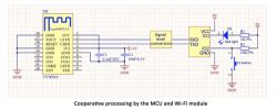
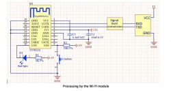
    TuyaMCU is a communication protocol used between the microcontroller and the WiFi module present in Tuya products:
    OpenBeken and TuyaMCU dimmer - configuration guide/tutorial
    OpenBeken and TuyaMCU dimmer - configuration guide/tutorial


    Purchase of a dimmer
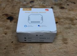
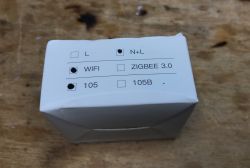
    I bought the product some time ago. It can be found by searching for MoesHouse DIY Smart WiFi Light LED Dimmer Switch Smart Life / Tuya APP Remote Control 1 Way Switch Works With Alexa Google Home - 1pcs . Now its price has probably increased a bit, but you can also find it cheaper on various websites:
    OpenBeken and TuyaMCU dimmer - configuration guide/tutorial
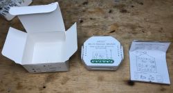
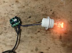
    The maximum power of lighting for this dimmer is 150W. The WiFi standard is 2.4GHz 802.11 b/g/n. It works with Tuya Smart / Smart Life applications. Its size is 51x46x22mm.
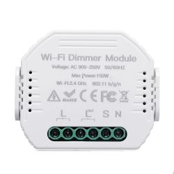
    OpenBeken and TuyaMCU dimmer - configuration guide/tutorial
    The set also includes instructions:
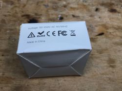
    OpenBeken and TuyaMCU dimmer - configuration guide/tutorial OpenBeken and TuyaMCU dimmer - configuration guide/tutorial
    OpenBeken and TuyaMCU dimmer - configuration guide/tutorial OpenBeken and TuyaMCU dimmer - configuration guide/tutorial
    OpenBeken and TuyaMCU dimmer - configuration guide/tutorial OpenBeken and TuyaMCU dimmer - configuration guide/tutorial

    The interior of the dimmer
    Now it's time to look inside.
    It is really easy to remove the casing.
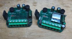
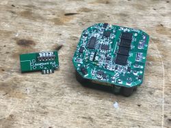
    Here, the photo gallery will be a bit unusual, because I also have the same dimmer damaged, I got it from one of our users, so I will put both in the photos
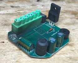
    OpenBeken and TuyaMCU dimmer - configuration guide/tutorial OpenBeken and TuyaMCU dimmer - configuration guide/tutorial OpenBeken and TuyaMCU dimmer - configuration guide/tutorial OpenBeken and TuyaMCU dimmer - configuration guide/tutorial
    Two dimmers next to each other, functional and damaged:
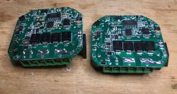
    OpenBeken and TuyaMCU dimmer - configuration guide/tutorial OpenBeken and TuyaMCU dimmer - configuration guide/tutorial
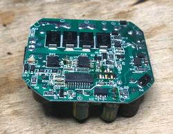
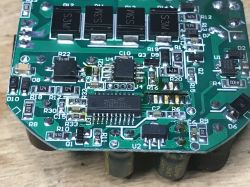
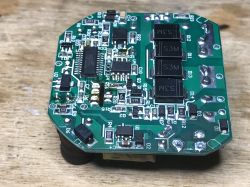
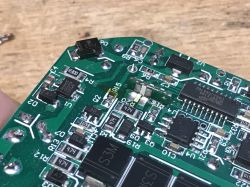
    What does the dimmer have inside? First of all, the WB2S WiFi module + Holtek HT66F3195 microcontroller. They communicate via UART.
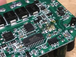
    OpenBeken and TuyaMCU dimmer - configuration guide/tutorial
    They are powered by BP2525 (transformerless power supply), and next to it we have a whole circuit associated with a dimmer (S3M rectifier diodes), an optocoupler to detect the sine cycle, an unmarked controller circuit and ... SIF12N65F. Originally I was expecting a triac here, but this is an N-channel MOSFET (Vds = 650V, RdsOn = 0.6Ohm, Id = 12A). This explains these four rectifier diodes. This dimmer apparently rectifies the mains voltage and then keyed it with a transistor.

    WB2S programming
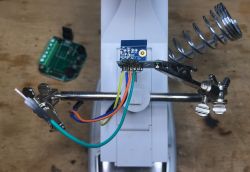
    I did the flashing just like in the previous topics in the series, by bkWriter 1.60.
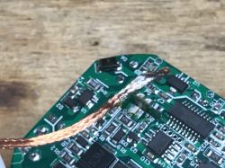
    I desoldered the WB2S from the board using a flux and a soldre wick. It's the easiest way for me because it makes sure that nothing on the RX / TX line will interfere with the loading of the firmware.
    OpenBeken and TuyaMCU dimmer - configuration guide/tutorial OpenBeken and TuyaMCU dimmer - configuration guide/tutorial OpenBeken and TuyaMCU dimmer - configuration guide/tutorial OpenBeken and TuyaMCU dimmer - configuration guide/tutorial OpenBeken and TuyaMCU dimmer - configuration guide/tutorial
    After that, you can run the OBK according to these topics:
    Qiachip Smart Switch - BK7231N / CB2S - interior, programming
    Light switch from the USA - Gosund Smart Switch SW5-A-V2.1 - BK7231T
    Garden Tuya CCWFIO232PK Double Relay - BK7231T - Programming

    OpenBeken configuration
    After the basic configuration that I discussed in the previous topics in the series, prepare a startup script (a file named autoexec.bat with the following content):
    Code: text
    Log in, to see the code

    And in the App panel, drag it to the OBK file system:
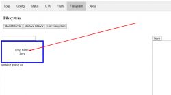
    OpenBeken and TuyaMCU dimmer - configuration guide/tutorial
    This script will execute after device boot. After dragging itself, it will not be executed, you have to restart device manually (e.g. with a button from the WWW panel).
    After uploading:
    OpenBeken and TuyaMCU dimmer - configuration guide/tutorial
    Meaning of individual commands:
    - startDriver TuyaMCU - runs the TuyaMCU driver
    - setChannelType 1 toggle - set the type of channel number 1 to On / Off
    - setChannelType 2 dimmer - sets the type of channel number 2 on the dimmer
    - tuyaMcu_setDimmerRange 0 1000 - sets the value range of the TuyaMCU dimmer (for GUI it is from 0 to 100 always, to 0 to 1000 it is converted only for MCU)
    - linkTuyaMCUOutputToChannel 1 bool 1 - connects TuyaMCU dpID number 1 with bool type channel number 1
    - linkTuyaMCUOutputToChannel 2 val 2 - connects dpID number 2 of TuyaMCU with channel number 2 of value type
    The dpID values can be different for different kinds of devices. If we want to add support for something new, we need to get to know it, e.g. by listening for packages. The dpID values can also be taken from the descriptions of devices intended for Tasmota, because Tuya often only changes the WiFi module and the rest remains the same.
    After a restart in the OpenBK panel, we have a separate switch and dimmer:
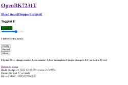
    OpenBeken and TuyaMCU dimmer - configuration guide/tutorial
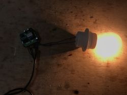
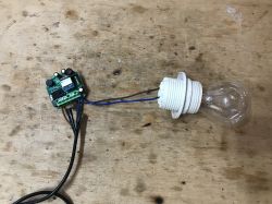
    This is how the different levels of brightness look like:
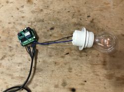
    OpenBeken and TuyaMCU dimmer - configuration guide/tutorial OpenBeken and TuyaMCU dimmer - configuration guide/tutorial OpenBeken and TuyaMCU dimmer - configuration guide/tutorial OpenBeken and TuyaMCU dimmer - configuration guide/tutorial

    How does the button work?
    At first glance, you might think that the button is not supported by OpenBeken. But nothing could be more wrong!
    In this product, the button is connected to the TuyaMCU, not to the module with WiFi. This TuyaMCU supports the button. We have everything ready. We connect the button to the appropriate pin (S for switch):
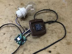
    OpenBeken and TuyaMCU dimmer - configuration guide/tutorial
    Both bistable and monostable buttons can be used. The button works in such a way that after switching on the brightness gradually increases and we can choose what level we want by simply switching it again. If, on the other hand, the light is on, the quick switching on and off of the button will turn it off completely. All of this is done by HT66F3195.


    Home Assistant support
    Pairing with Home Assistant is very simple, all thanks to the automatic mapping of OpenBeken channels to TuyaMCU variables. The TuyaMCU dimmer is operated from the HA level in the same way as an ordinary PWM-based dimmer. Here is a sample Yaml code:
    Code: yaml
    Log in, to see the code

    We have two separate channels - one determines the state of the device (on / off), the other - the brightness level.
    Final application test:
    [movie: 9a87cdbc15] https://filmy.elektroda.pl/95_1654602681.mp4 [/ movie: 9a87cdbc15]
    Final button test:
    [movie: 9a87cdbc15] https://filmy.elektroda.pl/4_1654602765.mp4 [/ movie: 9a87cdbc15]
    What is noticeable in the movies? First of all, a step-by-step animation of the brightness shift that comes from Holtek's layout and cannot be changed. This is why the Home Assistant slider "clicks".
    Also, there is a slight delay in reporting the status, but that's normal.

    Support for scripts and commands over HTTP
    OpenBeken supports sending Tasmota-style commands via the so-called "Tasmota HTTP". You can even send them via an ordinary browser.
    This command will turn the lamp on at full brightness:
    
    http://192.168.0.115/cm?cmnd=backlog%20setChannel%201%201;%20setChannel%202%20100
    

    The one at 50% brightness:
    
    http://192.168.0.115/cm?cmnd=backlog%20setChannel%201%201;%20setChannel%202%2050
    

    It will turn it off after 5 seconds:
    
    http://192.168.0.115/cm?cmnd=addRepeatingEvent%205%201%20setChannel%201%200
    

    (addRepeatingEvent syntax: repetition period, number of repetitions, command)
    There are also commands that add a value to the current brightness value, for example, but more on that another time.

    Related topic
    TuyaMCU is used in many devices, it also can be found in WiFi / RF433MHz fan controller. I recommend reading the topic:
    QIACHIP Universal WIFI Ceiling Fan Light Remote Control Kit - BK7231N - CB2S


    Summary
    It seems that TuyaMCU is already well supported. Everything works well with MQTT and Home Assistant (along with both-way communication and status updates), and even allows you to script simple automations within OpenBeken itself.
    Soon I will test more devices from TuyaMCU and also add more possibilities for the command interpreter (maybe possibility to execute simple scripts).
    PS: And if you are interested in a slightly different dimmer with a different UART protocol (no longer TuyaMCU, but a different text protocol), please read this topic .

    Cool? Ranking DIY
    About Author
    p.kaczmarek2
    Moderator Smart Home
    Offline 
    p.kaczmarek2 wrote 5843 posts with rating 5827, helped 279 times. Been with us since 2014 year.
  • #3
    p.kaczmarek2
    Moderator Smart Home
    A very interesting suggestion. Thanks, I haven't seen this before.

    The only thing I do not like is that under the BK7252 password in Google, this topic from the HA forum is second and there is some (fortunately) documentation and SDK ... but this proves that BK7252 is not popular and is not used in many devices. And if it is not popular, it has a lower priority than, for example, support for WiFi systems from Realtek, type WBR3, WBR2, etc.

    Well, okay, you convinced me, I bought one A9 mini camera and we'll see what it will be when the package arrives.
  • #4
    austin007
    Level 17  
    @ p.kaczmarek2 Super. I see you put in a lot of effort, there are results and you share them! - You like SoC Beken :) It is known that producers are looking for savings. BK is cheaper than Realtek and hence the choice. I'm more interested in zigbee devices, but streaming requires something else. The camera is cheap, it has some power, IR and motion detection as well as SD card recording. If we could keep these functionalities and enable integration with HA, it would be a very interesting solution.
    The picture itself probably does not break anything, but at this price. I just ordered it, so I don't know which converter is there. I would still lack a Lan connection to monitor the parking space in the underground garage, ... but not the cash register.
  • #5
    noel200
    Level 26  
    Have you heard of something like Supla? I recently bought a Nous A1 socket. It was supposed to be a gosund sp111 clone on the ESP8266 / 8285 and there was a BK chip in the middle. What are the differences to esp? Can you upload the firmware from ESP to BK?
  • #6
    efaden
    Level 5  
    Ever tried it with the two channel dimmer? Trying to get that to work, but can't figure out how to configure it correctly.
  • #7
    p.kaczmarek2
    Moderator Smart Home
    Well, then you should create two separate channels for two separate fnIds.

    What kind of dimmer do you have?
  • #9
    p.kaczmarek2
    Moderator Smart Home
    Well, I think there should be no problems, but do you know the dpIds of each of two dimmer channels?

    You need something like that:
    
    startDriver TuyaMCU
    setChannelType 1 toggle
    setChannelType 2 dimmer
    setChannelType 3 toggle
    setChannelType 4 dimmer
    tuyaMcu_setDimmerRange 0 1000
    linkTuyaMCUOutputToChannel 1 1 1
    linkTuyaMCUOutputToChannel 2 2 2
    linkTuyaMCUOutputToChannel 3 1 3
    linkTuyaMCUOutputToChannel 4 2 4
    

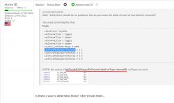
    NOTE: the syntax is linkTuyaMCUOutputToChannel dpId varType channelID, varTypes are such:
    OpenBeken and TuyaMCU dimmer - configuration guide/tutorial
  • #10
    rtrabold
    Level 2  
    Hi,
    I have a GIRIER Tuya 1 Channel Dimmer like the posted here:
    https://github.com/arendst/Tasmota/discussions/14506
    Only difference is that it came with a CB3S module. I sucessfully flashed OpenBeken on it.
    The issue now is to find correct TuyaMCU configuration, dpIds and function. Any clue about it?
    Tested with:

    startDriver TuyaMCU
    setChannelType 1 toggle
    setChannelType 2 dimmer
    tuyaMcu_setDimmerRange 0 1000
    linkTuyaMCUOutputToChannel 1 1 1
    linkTuyaMCUOutputToChannel 2 2 2


    But nothing happens.
    Any way to find working dpIs?
  • #11
    efaden
    Level 5  
    p.kaczmarek2 wrote:
    Well, I think there should be no problems, but do you know the dpIds of each of two dimmer channels?

    You need something like that:
    
    startDriver TuyaMCU
    setChannelType 1 toggle
    setChannelType 2 dimmer
    setChannelType 3 toggle
    setChannelType 4 dimmer
    tuyaMcu_setDimmerRange 0 1000
    linkTuyaMCUOutputToChannel 1 1 1
    linkTuyaMCUOutputToChannel 2 2 2
    linkTuyaMCUOutputToChannel 3 1 3
    linkTuyaMCUOutputToChannel 4 2 4
    

    NOTE: the syntax is linkTuyaMCUOutputToChannel dpId varType channelID, varTypes are such:
    OpenBeken and TuyaMCU dimmer - configuration guide/tutorial


    Is there a way to determine those? I don't know them...

    The tasmota config is

    
    {"NAME":"WM-105","GPIO":[0,2272,0,2304,0,0,0,0,0,0,0,0,0,0],"FLAG":0,"BASE":54,"CMND":"TuyaMCU 11,1 | TuyaMCU 21,2 | TuyaMCU 12,7 | TuyaMCU 22,8 | DimmerRange 0,1003"}


    Added after 4 [minutes]:

    Looks like 1 and 2 are the switches and 7 and 8 are the dimmers. Unless they changed when they moved from the esp.
  • #12
    p.kaczmarek2
    Moderator Smart Home
    efaden wrote:

    Looks like 1 and 2 are the switches and 7 and 8 are the dimmers. Unless they changed when they moved from the esp.

    I think you might be correct here. Please try.

    Remember that you can also just look at the logs in OpenBeken console, maybe enable debug logging (type loglevel 7 in console and then ALSO change the dropdown to "All" in console). If some kind of information from logging is missing, I can add it for you.
  • #13
    efaden
    Level 5  
    p.kaczmarek2 wrote:
    efaden wrote:

    Looks like 1 and 2 are the switches and 7 and 8 are the dimmers. Unless they changed when they moved from the esp.

    I think you might be correct here. Please try.

    Remember that you can also just look at the logs in OpenBeken console, maybe enable debug logging (type loglevel 7 in console and then ALSO change the dropdown to "All" in console). If some kind of information from logging is missing, I can add it for you.


    What are the 3 variables for linkTuyaMCUOutputToChannel? The documentation doesn't actually specify what they are.
  • #14
    p.kaczmarek2
    Moderator Smart Home
    @efaden nice spot, it was indeed missing from readme, although in this very topic it was said what they are:
    OpenBeken and TuyaMCU dimmer - configuration guide/tutorial
    Still, thank you for reporting. I also updated the readme on git.
  • #15
    efaden
    Level 5  
    p.kaczmarek2 wrote:
    @efaden nice spot, it was indeed missing from readme, although in this very topic it was said what they are:
    OpenBeken and TuyaMCU dimmer - configuration guide/tutorial
    Still, thank you for reporting. I also updated the readme on git.


    Totally missed that. Thanks!
  • #16
    p.kaczmarek2
    Moderator Smart Home
    If you can see something else missing from the readme on git, please also report it to me. This readme should be complete.
  • #17
    efaden
    Level 5  
    p.kaczmarek2 wrote:
    If you can see something else missing from the readme on git, please also report it to me. This readme should be complete.


    Will do. The config that is built in for the Moe's 4 Gang also has some issues. The pins weren't assigned correctly. I think I figured out the correct ones though. Not sure if you wanted to look at the ones in the template.
  • #18
    rtrabold
    Level 2  
    rtrabold wrote:
    Hi,
    I have a GIRIER Tuya 1 Channel Dimmer like the posted here:
    https://github.com/arendst/Tasmota/discussions/14506
    Only difference is that it came with a CB3S module. I sucessfully flashed OpenBeken on it.
    The issue now is to find correct TuyaMCU configuration, dpIds and function. Any clue about it?
    Tested with:

    startDriver TuyaMCU
    setChannelType 1 toggle
    setChannelType 2 dimmer
    tuyaMcu_setDimmerRange 0 1000
    linkTuyaMCUOutputToChannel 1 1 1
    linkTuyaMCUOutputToChannel 2 2 2


    But nothing happens.
    Any way to find working dpIs?


    After a bit of UART sniffing, it seems that the MCU is not responding.
    WiFi module keep sending hearbeat but MCU doesnt respond.
    I flashed OpenBeken withou disconnect MCU from CB3S, it possible that MCU "firmware" got corrupt during BK7231N flashing?.

    Weird thing is that I sent "55 aa 00 01 00 00 00" (including spaces) using OpenBeken UART Tool and lights turn on but OpenBeken do not receive any response from MCU. Then realiced that real data sent to MCU was "55 0A F0 00 00 F0 00 00 F0 00 2F", not even close to what is a correct TuyaMCU packet, so not sure what is happening.

    @p.kaczmarek2 Any idea about what could be happening? also any chance to log sent/received UART packets in OpenBeken console?
    great work!
  • #19
    francuz1222
    Level 1  
    efaden wrote:
    p.kaczmarek2 wrote:
    Well, I think there should be no problems, but do you know the dpIds of each of two dimmer channels?

    You need something like that:
    
    startDriver TuyaMCU
    setChannelType 1 toggle
    setChannelType 2 dimmer
    setChannelType 3 toggle
    setChannelType 4 dimmer
    tuyaMcu_setDimmerRange 0 1000
    linkTuyaMCUOutputToChannel 1 1 1
    linkTuyaMCUOutputToChannel 2 2 2
    linkTuyaMCUOutputToChannel 3 1 3
    linkTuyaMCUOutputToChannel 4 2 4
    

    NOTE: the syntax is linkTuyaMCUOutputToChannel dpId varType channelID, varTypes are such:
    OpenBeken and TuyaMCU dimmer - configuration guide/tutorial


    Is there a way to determine those? I don't know them...

    The tasmota config is

    
    {"NAME":"WM-105","GPIO":[0,2272,0,2304,0,0,0,0,0,0,0,0,0,0],"FLAG":0,"BASE":54,"CMND":"TuyaMCU 11,1 | TuyaMCU 21,2 | TuyaMCU 12,7 | TuyaMCU 22,8 | DimmerRange 0,1003"}


    Added after 4 [minutes]:

    Looks like 1 and 2 are the switches and 7 and 8 are the dimmers. Unless they changed when they moved from the esp.


    Did you figure out the correct setup for the 2 gang dimmer ?
  • #20
    efaden
    Level 5  
    francuz1222 wrote:
    efaden wrote:
    p.kaczmarek2 wrote:
    Well, I think there should be no problems, but do you know the dpIds of each of two dimmer channels?

    You need something like that:
    
    startDriver TuyaMCU
    setChannelType 1 toggle
    setChannelType 2 dimmer
    setChannelType 3 toggle
    setChannelType 4 dimmer
    tuyaMcu_setDimmerRange 0 1000
    linkTuyaMCUOutputToChannel 1 1 1
    linkTuyaMCUOutputToChannel 2 2 2
    linkTuyaMCUOutputToChannel 3 1 3
    linkTuyaMCUOutputToChannel 4 2 4
    

    NOTE: the syntax is linkTuyaMCUOutputToChannel dpId varType channelID, varTypes are such:
    OpenBeken and TuyaMCU dimmer - configuration guide/tutorial


    Is there a way to determine those? I don't know them...

    The tasmota config is

    
    {"NAME":"WM-105","GPIO":[0,2272,0,2304,0,0,0,0,0,0,0,0,0,0],"FLAG":0,"BASE":54,"CMND":"TuyaMCU 11,1 | TuyaMCU 21,2 | TuyaMCU 12,7 | TuyaMCU 22,8 | DimmerRange 0,1003"}


    Added after 4 [minutes]:

    Looks like 1 and 2 are the switches and 7 and 8 are the dimmers. Unless they changed when they moved from the esp.


    Did you figure out the correct setup for the 2 gang dimmer ?


    Not yet. Had to fix some other stuff and it got put on the back burner for a minute
  • #21
    MotoSpeed
    Level 4  
    @francuz1222 I'm just a beginner, so not sure how much I can help, but I recently had to find this information on a different device.

    Go in the web address of your device, then click "Launch Web Application," click on the "Logs" tab, set the "Log Level" to debug, uncheck every box except "CMD" and "TuyaMCU," press the "Clear" button under Logging, enter/submit the following commands one at a time:
    startDriver TuyaMCU
    tuyaMcu_sendQueryState
    
    After submitting the commands, press the "Pause" button under Logging, highlight the contents of the log, and past it into a notepad.

    Now look through the log to find the dpId and dataType, example shown below:
    Debug:CMD:cmd [tuyaMcu_sendQueryState]
    Info:TuyaMCU:TUYAMCU received: 55 AA 03 07 00 05 01 01 00 01 00 11 
    Info:TuyaMCU:TuyaMCU_ProcessIncoming[ver=3]: processing command 7 (State) with 12 bytes
    -->Info:TuyaMCU:TuyaMCU_ParseStateMessage: processing dpId 1, dataType 1-DP_TYPE_BOOL and 1 data bytes<--
    Info:TuyaMCU:TuyaMCU_ParseStateMessage: raw data 1 byte: 
    Info:TuyaMCU:TUYAMCU received: 55 AA 03 07 00 08 02 02 00 04 00 00 03 E8 04 
    Info:TuyaMCU:TuyaMCU_ProcessIncoming[ver=3]: processing command 7 (State) with 15 bytes
    -->Info:TuyaMCU:TuyaMCU_ParseStateMessage: processing dpId 2, dataType 2-DP_TYPE_VALUE and 4 data bytes<--
    Info:TuyaMCU:TuyaMCU_ParseStateMessage: raw data 4 int: 1000
    In this example, we have a dpId 1 with a datatype 1-bool, and a dpId 2 with a datatype 2-value. The Tasmota TuyaMCU documentation tells use the following:
    Boolean (bool): non-true or false binary variable, such as: switch function, on / off
    Value (value): suitable for linear adjustment of the type of data, such as: temperature regulation, temperature range 20-40 ℃
    Enum (enum): custom finite set value, such as: working levels, low / mid / high
    
    The datatype 1-bool can be used as a switch function, on/off, so we will assign a channel type as toggle. The datatype 2-value is a linear adjustment as use for temperature or dimmer functions, so we will assign a channel type as dimmer. We assign channel types with the following command:
    setChannelType [channel Number] [Channel Type]
    I don't think that the channel number mean anything at this point, 1 could have been dimmer and 2 toggle, just go in consecutive order

    We should have all the information we need to now create the commands needed.
    We need to assign 1 channel to be a toggle, and 1 to be a dimmer. This is how that will look.
    setChannelType 1 toggle
    setChannelType 2 dimmer
    Since a Tasmota config was given with a dimmer range, 0,1003, we'll use that in the following command:
    tuyaMcu_SetDimmerrange 0 1003


    Now we need to link the dpId to the channels that we just assigned, the OpenBeken readme shows that we do this in the following format
    linkTuyaMCUOutputToChannel [dpId] [varType] [ChannelID]

    We have a dpId of 1, with a varType of 1-bool, and we'll be linking it to channel 1 from earlier in the following command:
    linkTuyaMCUOutputToChannel 1 1 1

    For the next one, we have a dpId of 2, with a varType of 2-value, and we'll link it to channel 2 from earlier in the following command:
    linkTuyaMCUOutputToChannel 2 2 2


    Our final commands would look like this:
    startDriver TuyaMCU
    setChannelType 1 toggle
    setChannelType 2 dimmer
    tuyaMcu_setDimmerRange 0 1003
    linkTuyaMCUOutputToChannel 1 1 1
    linkTuyaMCUOutputToChannel 2 2 2 
    You can execute each command by themselves, and test that everything is functioning, or you can go ahead and create your autoexec.bat file.

    I hope that this will help you locate the needed dpId and varType information needed, and to better understand the formatting needed in each command. If you're still struggling, post the log information after running the command “tuyaMcu_sendQueryState” and I’ll try to help.
  • #22
    p.kaczmarek2
    Moderator Smart Home
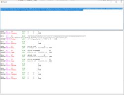
    I am working on TuyaMCU analyzer tool. The tool just helps out to make packets more human-readable. If you capture the packets between TuyaMCU and WiFi module with original firmware, it can help you determine dpIDs. It might be worth to capture data on RX/TX before flashing obk.

    Here is the screenshot:
    OpenBeken and TuyaMCU dimmer - configuration guide/tutorial
    As you can see, device makes dpID clearly visible (or fnIDs, maybe i named it wrongly...)
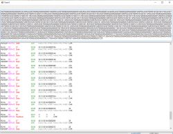
    Here is another screenshot. Capture of TuyaMCU data while dimming. You can clearly see which ID is the dimmer. You can see that values are within 0-1000 range.
    OpenBeken and TuyaMCU dimmer - configuration guide/tutorial
    I will be releasing this tool soon.

    Btw: @MotoSpeed great writeup! thanks!
  • #23
    MotoSpeed
    Level 4  
    p.kaczmarek2 wrote:
    Btw: @MotoSpeed great writeup! thanks!

    Thank you


    p.kaczmarek2 wrote:
    I am working on TuyaMCU analyzer tool.


    @p.kaczmarek2 I'm not sure if this would be of any help, but while I was struggling to locate the dpId information for an unknown device, I had read some of the documentation for Tasmota, and it had suggested using a booklet called Tasmota Tuya MCU Helper. It of course didn't work with OpenBeken, but the video looks like it's really user friendly, and even handles the programming for the user. I'm not sure how difficult it would be to modify this to work with OpenBeken, but from a user standpoint it would be very helpful.
  • #24
    Tamadite
    Level 1  
    p.kaczmarek2 wrote:
    A very interesting suggestion. Thanks, I haven't seen this before.

    The only thing I do not like is that under the BK7252 password in Google, this topic from the HA forum is second and there is some (fortunately) documentation and SDK ... but this proves that BK7252 is not popular and is not used in many devices. And if it is not popular, it has a lower priority than, for example, support for WiFi systems from Realtek, type WBR3, WBR2, etc.

    Well, okay, you convinced me, I bought one A9 mini camera and we'll see what it will be when the package arrives.

    I'm the author of that post in HA about the BK7252 A9 camera. I got here searching for hacking info on this device. I'm looking forward to hearing from your project about it. :)
  • #25
    p.kaczmarek2
    Moderator Smart Home
    @Tamadite Hello, I remember reading your post. I have currently two such cameras, if I remember correctly, one has broken out both UART and SPI interfaces and I managed to read and write it's flash with bkWriter, but didn't have time to compile the SDK for that one yet, and the second one sadly has no pins broken out for easy flashing. Futhermore, if I remember correctly, my first one now has broken bootloader and I will need to use my SPI method to retrieve it. Details here:
    BK7231 programming via SPI in flash memory mode - Python and Banana Pi

    btw both my cameras were bought on ebay, both were marked A9 but still they were using two different mobile apps...
  • #26
    austin007
    Level 17  
    @p.kaczmarek2
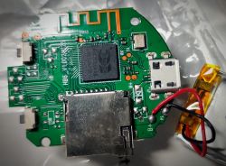
    It seems to me that all cameras, despite the different software supporting hardware, are the same. I had a few pieces in my hand and it was the same. Mine looks like attachment BK7252. Most likely the batches are very similar/identical and differ in communication/keys per app. I'm looking for opportunities myself and I'm rooting for this topic. It would be great to open it to HA. For me, even though I ordered the option with IR from majfiend, I got it without. I waved my hand because the camera itself works. Which is not so obvious either. I have no pads near the microswitches. I do not know what functionalities these circuits are responsible for and whether they are supported in the software. Maybe decompiling the batch would help.
    OpenBeken and TuyaMCU dimmer - configuration guide/tutorial
  • #27
    p.kaczmarek2
    Moderator Smart Home
    @austin007 I see RX and TX pads, are there any pads on the other side of the PCB too?
  • #28
    austin007
    Level 17  
    @p.kaczmarek2
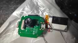
    I haven't seen the other one. But here is Rx, Tx and the other 3 pads + 2 described below. I thought you were undressing yours. Are they different or have you taken them apart? I haven't come across any other performance. There is a LION charger chip, passive elements for the image sensor, sockets. leds, microphone and points L+, L- maybe it's for IR lighting which I don't have.

    OpenBeken and TuyaMCU dimmer - configuration guide/tutorial
  • #29
    p.kaczmarek2
    Moderator Smart Home
    @austin007 as I wrote above - I bought two such cameras and each had a different app and PCB. One had all the signals on the test pads (along with SPI, which is a plus) and the other probably did not have any signals at all. So I'm curious what version you have.
  • #30
    nelevit
    Level 2  
    @p.kaczmarek2 Your project rescued my phone from another shady chinese app, thanks a lot!

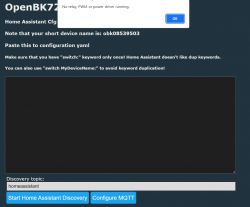
    Would you be able to give me a hint on this pop up message?
    OpenBeken and TuyaMCU dimmer - configuration guide/tutorial

    I am trying to add dimmer to HA (MOES wifi dimmer BK7231N configured via autoexec.bat from example, works great), but despite MQTT settings are configured, can't enable Autodiscovery :(

    Thanks in advance,

    Best regards,
    Nestor