logo elektroda
logo elektroda
X
logo elektroda

[Solved] [BK7231N/CB2S] Inverted PCB layout of CB2S on FS-05R Mini Dimmable Switch

iotflasher 3129 28
ADVERTISEMENT
  • #1 21004711
    iotflasher
    Level 2  

    I bought a couple of cheap Aliexpress Mini Dimmable (FS-05R) switches, hoping to either flash OpenBeken, or at worst replace the CB2S with an ESP alternative.
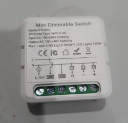
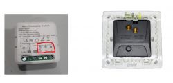
    Mini Dimmable Switch model FS-05R with technical information on the casing.
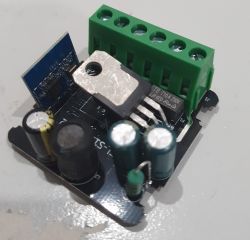
    Photo of an electronic module with components such as capacitors, a green terminal block, and a blue module labeled CB2S.
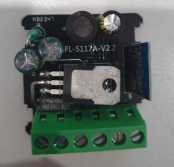
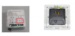
    PCB model: FL-S117A-V2.2
    Image of PCB model FL-S117A-V2.2 with various electronic components, including capacitors and a green connector.
    PCB of FS-05R switch from Aliexpress

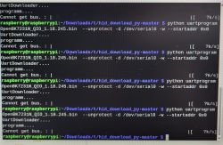
    Having desoldered the CB2S and connected to a USB-TTL there was no response to the BekenWriter and no amount of shorting the CEN pin to ground (or the CSN pin) made any difference.

    Watching the serial data, the device seems to just spam
    <0xff><0xff><0xff>......
    to eternity.
    That on both the TX1/RX1 pins as well as the TX2/RX2 pin

    Giving up, I decided to replace the chip with an ESP or other alternative, only to notice that the entire PCB seems to be printed mirror imaged to all the documentation.

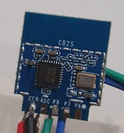
    All data I find on the internet shows the CB2S pins: 3V3 - GND - RX1 - TX1 - P24 - P26 from left to right, this one seems to be same order, but right to left.
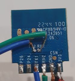
    Close-up view of a PCB with connected wires.
    PCB labeled CB2S with visible components and connecting wires.
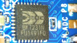
    Close-up of a Beken chip on a blue PCB.
    Also noting that the RX is actually labelled 'RX2', not 'RX1', I assume that's a typo.

    The mirroring makes any replacement, with something like an ESP-02S TYWE2S impossible.

    Has anyone come across this before?
    Is there something I'm missing?

    Also I've successfully flashed CB3S chips with OpenBeken in the past, so I'm not sure what I'm doing wrong here.
  • ADVERTISEMENT
  • Helpful post
    #2 21005220
    p.kaczmarek2
    Moderator Smart Home
    Yes. I know this issue. I have experienced it myself already at least two times before.
    For example, in this topic:
    https://www.elektroda.com/rtvforum/topic4039890.html
    which is, actually, also about the FS-05R.
    The silkscreen on this device is incorrect. You need to ignore that.
    You need to assume the classic pinout like on Tuya docs:
    Quote:

    Interior of the FS-05R
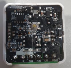
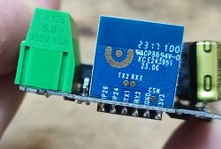
    The first thing that catches your eye after looking inside is: invalid CB2S description layer : :
    Close-up of a blue PCB with a green screw terminal block and visible silkscreen showing pins.
    Location of 3.3V (VDD) and GND is incorrect .
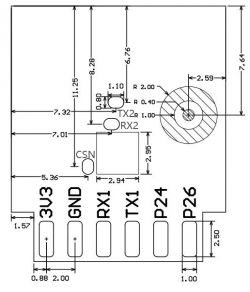
    I`ve checked it many times, and it`s not the first time I`ve come across a poorly described CB2S, and I know that the correct schedule is available on the Tuya website:
    Pin layout diagram with dimensions for an electronic module.
    Helpful post? Buy me a coffee.
  • ADVERTISEMENT
  • #3 21007004
    iotflasher
    Level 2  
    Oh wow.
    So simple, so logical and yet, I don't think I would have thought of this myself.

    But for anyone with the problem in the future....ignore the screen print, go with the connections as per datasheet.

    Thank you, and you've also just solved the next step of figuring out the TuyaMCU comms with your link.
  • #4 21007009
    p.kaczmarek2
    Moderator Smart Home
    I am happy to hear that it helped. I was also very confused at first, but then I remembered the good way to check the silkscreen - investigate the power connection on the PCB. Once you investigate how is 3.3V and GND connected, you will clearly see that silkscreen is invalid.

    Let me know if my script for this dimmer works for you
    Helpful post? Buy me a coffee.
  • #5 21014712
    iotflasher
    Level 2  
    The autoexec.bat script worked beautifully.
    A simple copy paste from your post and the dimmer worked as should.
    Thank you

    I did also add a couple of features (double click, click hold, etc) for the buttons.
    Making it work reliably from remote, as from local.

    My final autoexec.bat:
    
    //Event handlers for the button
    addEventHandler OnClick 24 setChannel 1 0
    addEventHandler OnClick 26 setChannel 1 1
    addEventHandler OnDblClick 24 backlog setChannel 2 15; setChannel 1 1
    addEventHandler OnDblClick 26 backlog setChannel 2 255; setChannel 1 1
    addEventHandler OnHold 24 addChannel 2 -5 0 255
    addEventHandler OnHold 26 addChannel 2 5 0 255
    
    // this is not really tuyaMCU but we will treat it as such
    startDriver TuyaMCU
    // set baud rate
    tuyaMcu_setBaudRate 115200
    
    // create a toggle and a dimmer
    setChannelType 1 toggle
    setChannelType 2 dimmer256
    
    
    // invoke refresh on change
    addEventHandler OnChannelChange 1 startScript autoexec.bat refresh
    addEventHandler OnChannelChange 2 startScript autoexec.bat refresh
    
    refresh:
    // channel 5 is temporary variable, from 0 to 255*3, multiplied also by toggle value
    setChannel 5 $CH2*3*$CH1
    // split into two bytes
    setChannel 3 $CH5/256
    setChannel 4 $CH5%256
    // send the two bytes
    tuyaMcu_sendCmd 0x30 00$CH3$$CH4$
    
    
  • #6 21200464
    zeronok2k
    Level 1  
    Hi. How about flashing using Tuya-Cloudcutter? Someone tried? Did it work? Thanks!!!
  • #7 21200557
    divadiow
    Level 34  
    zeronok2k wrote:
    How about flashing using Tuya-Cloudcutter?

    Cloudcutter success will depend on the firmware version. I see no mention of the versions the device in each thread came with. Do you know your version? have you dumped the firmware?
  • #8 21200772
    ferbulous
    Level 18  
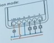
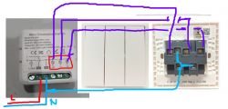
    Hi, how do you connect the dimmer to a momentary switch (with single pole)?
    Do you mind sharing the wiring connection? I'm not quite sure how to connect the 'power' terminal next to the '-' terminal.

    The image shows a mini dimmer switch and a single-pole momentary switch with connection terminals.

    Also, thanks for confirming that multipress works with tuya mcu, so you just can't decouple the relay for this dimmer right?
  • #9 21200780
    p.kaczmarek2
    Moderator Smart Home
    This is not a TuyaMCU device. It's using a custom protocol that has also UART packet similiar to the MCU one. Please check out the reverse-engineering topic:
    https://www.elektroda.com/rtvforum/topic4039890.html
    The multipress here is using standard GPIO button, not a TuyaMCU one.
    You can decouple anything here. The dimmer control is done by script, here:
    
    // send the two bytes (this is TuyaMCU command but protocol actually is a simpler one, it's not classic TuyaMCU)
    tuyaMcu_sendCmd 0x30 00$CH3$$CH4$
    

    Let me know what exactly you want to achieve and I will try to help.
    Helpful post? Buy me a coffee.
  • #10 21200782
    ferbulous
    Level 18  
    @p.kaczmarek2 thanks, i thought all tuya dimmers use tuya mcu.
    I just need to figure how to wire it to momentary switch since I plan to use it for 2 way
  • #11 21200816
    p.kaczmarek2
    Moderator Smart Home
    Wire it as in manual:
    https://obrazki.elektroda.pl/3676728400_1709365334.jpg
    and then set the role for appropriate OBK pin to "Button", I guess...
    Helpful post? Buy me a coffee.
  • #12 21201297
    ferbulous
    Level 18  
    @p.kaczmarek2
    Yes, there’s the manual but it’s not too clear how to wire the ‘power’, ‘+’ and ‘-‘ to the 1 gang switch with only 2 terminals
  • #13 21201401
    p.kaczmarek2
    Moderator Smart Home
    What do you mean by 2 terminals, can you show the photos of the device you have?

    Otherwise, just wire as in manual, keep in mind that there will be 3 GPIOs of BK7231 that you can later script to do whatever you want. Those GPIOs connects to the WiFi module, not to the MCU. They are configurable in OpenBeken.
    Helpful post? Buy me a coffee.
  • ADVERTISEMENT
  • #14 21201786
    ferbulous
    Level 18  
    @p.kaczmarek2 hi, it’s this pic I posted in previous post
    It’s a 1 gang momentary switch with 2 terminals in the back, unless i need a different switch for the dimmer

    Mini dimmer and momentary switch at the back with two terminals.
  • #15 21201830
    p.kaczmarek2
    Moderator Smart Home
    Sure, so the configuration steps are:
    1. turn off the power
    2. connect a momentary switch between gpio output and N, like on image:
    Wiring diagram of a momentary switch to GPIO terminals.

    So there will be only two wires to the switch and switch will connect them when pressed.

    3. in OBK, set the Button role for the appropriate pin. You can also try using GPIO doctor if you are not sure which pin is used. But, as far as I know:
    Code: JSON
    Log in, to see the code

    so if "plus" pin is 26, then you can connect momentary switch as I said to 26, and it should work with Button role in obk. You can also use dInput role for debugging.

    Please try the following steps and let me know if it works, if not, we'll investigate.
    Helpful post? Buy me a coffee.
  • #16 21202968
    ferbulous
    Level 18  
    @p.kaczmarek2
    Hi, is this the correct way to wire to the switch?
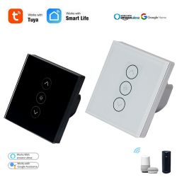
    It looks like I’ll need to use 3 button switch similar to other tuya dimmers for separate power, brightness up and dimming

    Two touch dimmer switches, black and white, compatible with Tuya, Smart Life, Amazon Alexa, and Google Home. Wiring diagram of a dimmer switch with highlighted wires.

    From the diagram it looks like the neutral’s bridged to the switch?
  • #17 21203044
    p.kaczmarek2
    Moderator Smart Home
    It seems ok. How your switch looks like from front? It has 3 momentary buttons?

    With some more scripting, it should be possible to use one button - click to turn on/off, hold to adjust brightness.
    Helpful post? Buy me a coffee.
  • ADVERTISEMENT
  • #18 21203935
    ferbulous
    Level 18  
    So I don’t think my unit working
    This is straight out of the box with stock firmware and wiring just neutral & live doesn’t seem to turn it on/no led
    I’ll have to claim for replacement
  • Helpful post
    #19 21203994
    p.kaczmarek2
    Moderator Smart Home
    It does not work when wired as in the manual?
    Helpful post? Buy me a coffee.
  • #20 21204002
    ferbulous
    Level 18  
    @p.kaczmarek2
    Haven’t wired it to the switch, but it doesn’t seem to turn on at all with just Lin and Nin wired.
  • #21 21204021
    p.kaczmarek2
    Moderator Smart Home
    Uh, sorry, I didn't read your message well! Now wait a minute.
    It does not have a relay, so you won't hear a click.
    Can you connect a classic, dimmable (a LED one won't work unless marked as dimmable) bulb to the output and try again? How does the panel look in the app?
    Helpful post? Buy me a coffee.
  • #22 21205179
    ferbulous
    Level 18  
    @p.kaczmarek2
    Doesn’t get detected by the app at all and there’s no led indicator blinking or anything.
    I’ve already got the refund, so I’ll open it up anyway if and flash openbeken if it does anything.
  • #23 21205363
    p.kaczmarek2
    Moderator Smart Home
    Maybe take a 2MB flash copy as well, and try to check the original Tuya bootlog. Interesting.
    Helpful post? Buy me a coffee.
  • #24 21206427
    ferbulous
    Level 18  
    @p.kaczmarek2
    Hi, looks like the dimmer boots up and connected to wifi.
    Probably it was stock firmware issue?
    Anyway, what do I assign for pin 24 & 26 before I use the script? Do I just set button 0 or 1 for pin 7
  • #25 21206747
    p.kaczmarek2
    Moderator Smart Home
    Very good!

    So, if you want to script button events, the best option is to use Btn_ScriptOnly role. It's a button role that casts events but does not automatically toggle relays.
    Helpful post? Buy me a coffee.
  • #26 21207752
    ferbulous
    Level 18  
    @p.kaczmarek2 since pin 24 & 26 are input buttons, is it possible to add rotary encoder like ky-040?
  • #27 21279972
    Spięcie
    Level 12  
    >>21206747 .

    Warm welcome,

    I am using a module to control a fan blowing heat from a fireplace with a small power of about 140W, quite nicely this solution works, but I would like to change the control range for example 70%-100%.
    this minimum value of 70% will allow the fan to start and protect it from damage/overheating.

    where is the code section for the adjustment range , look for it in autoexec.bat ? - thank you for your help,

    kind regards
  • #28 21333187
    fortunatornforty76
    Level 2  
    >>21004711

    FS-02HW mini Smart switch also has CB2S Wi-Fi module with wrong silkscreen

Topic summary

The discussion revolves around the challenges faced when attempting to flash OpenBeken or replace the CB2S chip in the FS-05R Mini Dimmable Switch. Users encountered issues with incorrect PCB silkscreen markings, leading to confusion about pin connections. It was advised to disregard the silkscreen and follow the classic pinout as per Tuya documentation. Successful scripting for the dimmer was shared, including event handlers for button actions. Users also explored alternative flashing methods like Tuya-Cloudcutter and discussed wiring configurations for momentary switches. Some users reported issues with device detection and functionality, prompting suggestions for troubleshooting and firmware flashing.
Summary generated by the language model.
ADVERTISEMENT