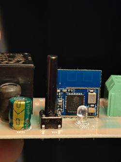
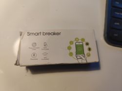
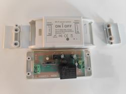
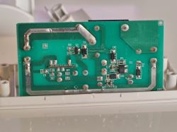
This is a 10A smart breaker that I got off AliExpress. It has an ESP8285 chip inside for which the GUI flashing tool didnt work, nor did cloudcutter. Software I believe was 1.1.8 but I have no way to check anymore and I forgot to write it down!
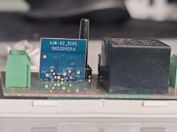
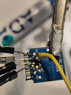
To flash the chip, I desoldered it from the pcb and connected rx, tx, 3.3v, gnd and gpio pins to a usb-uart ttl converter. I tried flashing without desoldering but think the capacitors messed up the timings..
I flashed the chip with EspHome using the EspHome wizard (see https://esphome.io/guides/getting_started_command_line.html) and extensive esphome docs to guide me. Finally, I flashed the following config.yaml after some trial and error to get the relay, button and wifi-led set up:
esphome:
  name: smartbreaker1

esp8266:
  board: esp8285

# Enable logging
logger:

# Enable Home Assistant API
api:
  password: ""

ota:
  password: ""

wifi:
  ssid: "
  password: ""

  # Enable fallback hotspot (captive portal) in case wifi connection fails
  ap:
    ssid: "Smartbreaker1 Fallback Hotspot"
    password: "BS8reTB8GQtJ"

captive_portal:

# Relay switch
switch:
  - platform: gpio
    name: "Smart Breaker Relay"
    pin: GPIO12
    id: relay

# Wifi-LED pin
status_led:
  pin:
    number: GPIO4
    #inverted: true

# Button pin
binary_sensor:
  - platform: gpio
    name: "Smart Breaker Button"
    pin:
      number: GPIO13
      mode: INPUT_PULLUP
    on_press:
      then:
        - switch.toggle: relay


