logo elektroda
logo elektroda
X
logo elektroda

[Solved] Successfully Flashing Luminea ZX-5140-675 LED Controller with OpenBK: A Detailed Guide

Dlay_71 1452 17
ADVERTISEMENT
  • Helpful post
    #1 20784937
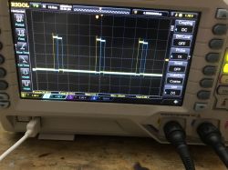
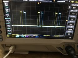
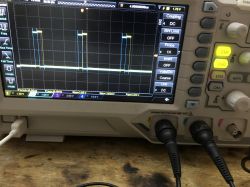
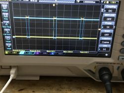
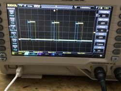
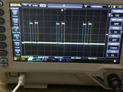
    Dlay_71
    Level 4  
    Hi,
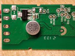
    i have flashed the Luminea ZX-5140-675 LED Controller with OpenBK successfully.
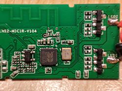
    The small Controller is based on BK7231N

    Here is how:

    1. Open the small case from the back
    2. Push out the PCB
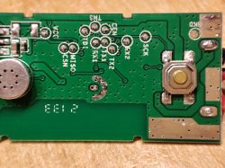
    3. Solder wires to VCC, GND, TX1, RX1
    4. Connect FTDI or simmilar to the corresponding wires you just soldered
    5. VCC is 3.3V !
    6. Use this BK7231 Flash Tool (description on the page itself): Link
    7. After flashing and connecting the device to your WiFi Network go to "Launch Web Application"
    8. Click the Tab "Import" and paste the following data under "Enter template here"

    {
    	"rstnum":"3",
    	"rstcor":"cw",
    	"Jsonver":"1.0.0",
    	"brightmin":"10",
    	"mic":"23",
    	"secpin_pin":"7",
    	"wfcfg":"spcl",
    	"firstpin_pin":"6",
    	"ledable":"0",
    	"pmemory":"0",
    	"adclimit":"2400",
    	"cmod":"cw",
    	"ismusic":"1",
    	"key_pin":"20",
    	"rstbr":"50",
    	"ktime":"3",
    	"lightstring":"[[scene1",
    	"module":"CBU",
    	"kswitch":"0",
    	"firstpin_lv":"1",
    	"cwmaxp":"100",
    	"rstmode":"1",
    	"secpin_lv":"1",
    	"brightmax":"100",
    	"key_lv":"0",
    	"deadtime":"200",
    	"pwmhz":"250",
    	"category":"1102",
    	"defcolor":"cw",
    	"crc":"84",
    	"}cJhAgw_di{abi":"0",
    	"id":"null",
    	"swv":"1.1.4",
    	"bv":"40.00",
    	"pv":"2.2",
    	"lpv":"3.3",
    	"pk":"keyy7twvusq5drjh",
    	"firmk":"keyy7twvusq5drjh",
    	"cadv":"1.0.3",
    	"cdv":"1.0.0",
    	"dev_swv":"1.1.4",
    	"s_id":"null",
    	"dtp":"0",
    	"sync":"0",
    	"attr_num":"0",
    	"mst_tp_0":"0",
    	"mst_ver_0":"null",
    	"mst_tp_1":"0",
    	"mst_ver_1":"null",
    	"mst_tp_2":"0",
    	"mst_ver_2":"null",
    	"mst_tp_3":"0",
    	"mst_ver_3":"null }3F1Awf_start_mdll",
    	"md":"0",
    	"random":"0",
    	"wfb64":"1",
    	"stat":"0",
    	"token":"null",
    	"region":"null",
    	"reg_key":"null",
    	"dns_prio":"03!  )@Agw_wsm{nc_tp",
    	"ssid":"null",
    	"passwd":"null",
    	"psk_key":"R7Uok9dIt85LdI7QuFu5D0ZVMtDmNG7pKkVNb",
    	"auth_key":"eULYRRr7iZh6NAPdUsu3AbAVNClmuhU0",
    	"ap_ssid":"SmartLife",
    	"ap_passwd":"null",
    	"country_code":"CN",
    	"bt_mac":"null",
    	"bt_hid":"null",
    	"prod_test":"false",
    	"fac_pin":"azf0uruabwr7fxyi }sKgAgw_ai{key",
    	"lckey":"null",
    	"h_url":"null",
    	"h_ip":"null",
    	"hs_url":"null",
    	"hs_ip":"null",
    	"hs_psk":"null",
    	"hs_psk_ip":"null",
    	"mqs_url":"null",
    	"mqs_ip":"null",
    	"mq_url":"null",
    	"mq_ip":"null",
    	"ai_sp":"null",
    	"ai_sp_ip":"null",
    	"mq_psk":"null",
    	"mq_psk_ip":"null",
    	"time_z":"null",
    	"s_time_z":"null",
    	"wx_app_id":"null",
    	"wx_uuid":"null",
    	"dy_tls_m":"0",
    	"cloud_cap":"0",
    	"psk21_key":"null }+{nc_tp"
    }
    

    9. Look for "Check generated script" which should say "OK! Generated."
    10. Press "Clear OBK and apply new script from above"
    11. Reboot the device (Power Cycle)
    12. Go to "Config" -> "Configure Module"
    13. Choose under P7 (PWM1) "PWM" and you are finally done.

    Now its possible to Switch the module on/off and change the brightness.

    Not working:
    Built in Microphone
    Switch Button in the Case

    I was not able to figure out how the button can be addressed.
    Pictures of the device can be found here: Link
    Pictures backup:
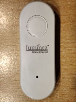
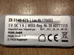
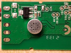
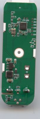
    White Luminea LED controller with logo on a wooden surface. Label of LED Luminea ZX-5140-675 with technical information. Close-up of the LED controller Luminea ZX-5140-675 circuit board with a microphone and port markings. Close-up of the LED controller Luminea ZX-5140-675 PCB with visible electronic components. Circuit board with a microphone and AMS1117 component. Close-up of the Luminea ZX-5140-675 LED controller PCB with visible traces, solder points, and a microphone.
  • ADVERTISEMENT
  • #2 20786794
    p.kaczmarek2
    Moderator Smart Home
    Thank you for this informative post.

    It seems that we can use JSON to extract GPIO information:
    
    	"mic":"23",
    	"secpin_pin":"7",
    	"firstpin_pin":"6",
    	"key_pin":"20",
    

    It seems that button may be on P20. You can set the pin role to Button and it will control the power of your LEDs, can you check?
    I can also see that mic may be on P23, it would make sense, it's ADC input.

    I am not sure why there are two more pins specific, as it seems your device is a single color strip controler? Or is it a CW device?
    Helpful post? Buy me a coffee.
  • #3 20788649
    Dlay_71
    Level 4  

    p.kaczmarek2 wrote:
    It seems that the button may be on P20. You can set the pin role to Button and it will control the power of your LEDs, can you check?
    I can also see that the mic may be on P23, it would make sense, it's an ADC input.

    I am not sure why there are two more pins specified, as it seems your device is a single color strip controller? Or is it a CW device?


    Hi there,

    Thanks for your time in this. I have tried your suggestions, but it doesn't react to P20 as a Button. I set P23 to ADC, but I don't know how to test the Mic. I would expect a displayed voltage change when the microphone captures audio, but I don't know how to see the values.

    Also, the controller behaves very strangely now. Pin 7 on PWM doesn't work anymore. Setting it to REL leads to the possibility to turn it ON/OFF. Previously, with PWM, I was able to control ON/OFF and brightness.

    Is there a way to reset OpenBK completely?

    I don't understand the meaning of "CW device," sorry.

    Attached are 100 very small LEDs on silver wire. They are organized in two channels, so with Pin7 I can only activate 50 of them. The other 50 stay dark, regardless of what I configure Pin6 to.
  • #4 20789576
    p.kaczmarek2
    Moderator Smart Home
    Would you be able to sketch a schematic how are those LEDs connected? Are those transistors pairs really connected to P6 and P7?
    Helpful post? Buy me a coffee.
  • ADVERTISEMENT
  • #5 20840416
    niclauser
    Level 4  
    Hello everyone, I would like to take up the topic again because I have been thinking about implementing this anti-parallel two-wire LED light chain with an ESP8266 and Tasmota for some time, but I can't do it. Now I specifically got the light chain from Iluminea because it already contains what I want to recreate, just with a BL7231. And with OpenBK I can also understand the software, analogous to Tasmota.

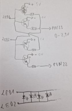
    The LED light chain is a two-wire LED chain in which the LEDs are alternately soldered in reverse. According to my knowledge, the control takes place via an H-bridge with 2x Y1, 2x Y2 transistors and 4x 1KOhm resistors. (see drawing) The H-bridge is controlled directly by BL7231 via its PIN 22 and 23. The control takes place via a quick switch between PIN22 and PIN23 (PIN22 - on > PIN23 - off, PIN22 - on > PIN23 - off). This creates the visual impression that the chain is flashing or the light is running. At the same time, the level of the voltage supplied by PIN22 and 23 is "changed" using PWM, which makes the LEDs appear brighter or darker. Using the button that switches PIN20 of the BL7231 directly to GND, a predefined scenario on the software side is switched to switching frequency between PIN22 and 23 and PWM brightness control (8 scenes, always in the order 1-9, 9=off).

    I leave out the control via music because it doesn't interest me.

    From my point of view, the problem is the permanent reciprocal control of the H-bridge from OpenBK (or from Tasmota, as I tried before). Basically I don't want running lights at all. Only the PWM PIN 22 and 23 must be activated at the same time and like a sine wave. How can I implement this?

    Best regards

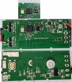
    Close-up of two views of circuit boards with various electronic components. H-bridge circuit diagram for controlling an LED chain.
  • #6 20840461
    p.kaczmarek2
    Moderator Smart Home
    Hello, so you want one PWM to be high when other is low? With a dead time?
    Hm, it seems that you need to use a PWM group. It's should be supported in our SDK, but it's not exposed on our GUI, as I haven't tested it yet. You are the first one to ask for that. Is this really a stock Tuya device? Still, I can try to write an OBK driver for that feature, if that's needed.
    Here's the required header:
    https://github.com/openshwprojects/OpenBK7231...s/beken378/func/user_driver/BkDriverPwm.h#L82
    Here are the function definitions you want:
    Code: C / C++
    Log in, to see the code

    So basically you'd need to initialise a PWMs pair with bk_pwm_group_initialize and then update their respective high times with bk_pwm_update_param.
    PS: See our current PWM HAL code for the reference:
    https://github.com/openshwprojects/OpenBK7231T_App/blob/main/src/hal/bk7231/hal_pins_bk7231.c
    Helpful post? Buy me a coffee.
  • #7 20840633
    niclauser
    Level 4  

    Hello Mr. Kaczmarek,

    First of all, thank you very much for this really quick answer.

    Quote:
    so you want one PWM to be high when the other is low? With a dead time?


    Yes, that is correct. Dead time, perhaps adjustable.

    Quote:
    Is this really a stock Tuya device?

    Tuya device, no idea. The manufacturer is Pearl from Germany. But it has to be based on Tuya since your BK7231 flasher can read the Tuya binary.

    I have attached a short video of the function. Maybe to understand why I want to solve the problem: I have several similar fairy lights, some up to 20m long. All of them are just "stupid", without WLAN control, only with a USB plug and blinking electronics. But the LED chain is constructed identically. Unfortunately, I cannot control this automatically. My plan was to recreate this control with an OpenBK or Tasmota so that I didn't have to throw away the fairy lights. A simple remote-controlled USB switch in front of it is not possible because the fairy lights start flashing wildly when switched on, and you first have to manually select a program, which is very bad.

    I like your solution approach. Fixed times would be enough for me. I don't need the program switches, although that would be a nice gimmick. I would like to try this out. Please help me:

    How do I get the required files integrated into the OpenBK after flashing? I'm not that deep in it yet.

    Thank you very much!


  • ADVERTISEMENT
  • #8 20840658
    p.kaczmarek2
    Moderator Smart Home
    niclauser wrote:

    I like your solution approach. Fixed times would be enough for me. I don't need the program switches, although that would be a nice gimmick. I would like to try this out.Please help me:

    How do I get the required files integrated into the OpenBK after flashing? I'm not that deep in it yet.

    The most simple and elegant way would be to create a new driver entry in drivers table, here:
    https://github.com/openshwprojects/OpenBK7231T_App/blob/main/src/driver/drv_main.c

    And then add a new driver file in drivers dir:
    https://github.com/openshwprojects/OpenBK7231T_App/tree/main/src/driver

    Then in driver init function setup PWM for two GPIOs (specified as arguments or somehow else) and in quick tick update maybe map two channel values to the PWM values.

    You may want to take a look at the code of other drivers for the reference.

    Alternatively, I may later find some time to do it for you. Currently I am implementing RN8209 support for a donator.
    Helpful post? Buy me a coffee.
  • #9 20886980
    p.kaczmarek2
    Moderator Smart Home
    Testing with scope.
    
    backlog startDriver PWMG; PWMG_Test
    

    Code: C / C++
    Log in, to see the code

    Oscilloscope screen displaying waveform signal.

    Same settings, but:
    Code: C / C++
    Log in, to see the code

    View of an oscilloscope screen displaying PWM signal waveforms.


    But I see a problem... it seems that duty2 argument is not even used in SDK:
    Code: C / C++
    Log in, to see the code


    Added after 1 [hours] 31 [minutes]:

    I am testing to see how it works....
    Following code:
    Code: C / C++
    Log in, to see the code

    gives me:
    Oscilloscope displaying PWM signal waveforms.

    Added after 6 [minutes]:

    Following code:
    Code: C / C++
    Log in, to see the code

    results:
    Oscilloscope screen displaying two synchronized PWM signals with dead time.

    Added after 8 [minutes]:

    Following code:
    Code: C / C++
    Log in, to see the code

    Result:
    View of Rigol oscilloscope screen with PWM signals

    Added after 8 [minutes]:

    Code:
    Code: C / C++
    Log in, to see the code

    Result:
    Oscilloscope display showing PWM waveforms on a RIGOL screen.
    Helpful post? Buy me a coffee.
  • ADVERTISEMENT
  • #10 20888314
    p.kaczmarek2
    Moderator Smart Home
    @Dlay_71 @niclauser PWM groups tutorial ready! https://www.elektroda.com/rtvforum/topic4025665.html#20888311
    Helpful post? Buy me a coffee.
  • #11 21334798
    2ya2
    Level 3  
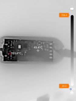
    Sorry for reviving an old thread but I think my observations may be relevant. I am happy to have found this thread. I successfully flashed my Luminea ZX-5140-675 LED Controller. What worries me, though, is that under full brightness a component on the PCB gets extremely hot. I measure up to 150 degrees Centigrade at full brightness and that's with just a 1 A USB power supply.

    I never noticed this before (also never measured). Is this still normal?
    Thermal image of a circuit board with a temperature of 159.4°C.
  • #12 21334802
    p.kaczmarek2
    Moderator Smart Home
    What's getting hot - MOSFETs, BK7231 or something else?

    BK7231 can use power save to reduce heating (PowerSave 1 in startup command or autoexec.bat).
    Helpful post? Buy me a coffee.
  • #13 21336018
    2ya2
    Level 3  
    p.kaczmarek2 wrote:
    What's getting hot - MOSFETs, BK7231 or something else?


    It is near the components at the "LED 2" label (if you compare my heat image and the fourth image in the top post). So it is not the BK7231. I lowered the brightness to 60 and then it is ok (around 50 or 60 °C).
  • #14 21336921
    p.kaczmarek2
    Moderator Smart Home
    Y2 transistor? It might mean that you have too long LED strip. Current consumption is too high.

    Did you get the controller in a set with a LED strip, or did you buy LED strip separately?
    Helpful post? Buy me a coffee.
  • #15 21337062
    2ya2
    Level 3  
    >>21336921 Thanks for the remark. It is an original strip, no modifications. Perhaps the original Tuya firmware did some limiting. Currently, I am figuring out which MQTT topics work and will make sure to keep the brightness low.

    Does "PowerSave 1" in startup only work for the chip, is there another limiter I could set?
  • #16 21346531
    2ya2
    Level 3  
    >>21337062
    Replying to myself, providing additional info.

    I bought another similar strip. With default firmware and full brightness the module also gets quite hot. So I just must make sure to not turn it all on.
  • #17 21347400
    p.kaczmarek2
    Moderator Smart Home
    150 degrees, if that's a correct measurement, it's way too much for such a device. It's a bad design on Tuya part. If you want to keep full brightness, consider shorting the LED strip, so it draws less current.
    Helpful post? Buy me a coffee.

Topic summary

The discussion revolves around successfully flashing the Luminea ZX-5140-675 LED Controller, which utilizes the BK7231N chip, with OpenBK firmware. The process involves opening the device, soldering connections to the PCB, and using a specific flashing tool. Users explore GPIO configurations, particularly for controlling LED brightness and functionality through PWM settings. Issues arise with pin configurations, particularly with the microphone and button functionalities, leading to inquiries about resetting the firmware and understanding the device's capabilities. Suggestions include creating a new driver for PWM group control to manage LED operations effectively. The conversation also touches on the potential for integrating similar LED chains with other firmware like Tasmota.
Summary generated by the language model.
ADVERTISEMENT