Hello everyone,
in this topic I'll explain to you, how you can flash OpenBeken (a.k.a. OpenBK7231T) to a LEDVANCE Smart+ (a.k.a. Smart WiFi Plug AC28208).
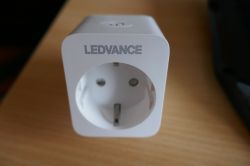
Personally I would estimate, that the difficulty of flashing OpenBeken to this device is rather high compared to other smart plugs, so you might want to reconsider. Anyway, make sure to read this post completely before you start and make sure that you understand all steps of this instruction and know how to perform them - I do assume at least some basic soldering & programming knowledge from your side!
Be sure that you have the following materials available, ideally before you start. Otherwise you might find yourself with a half-disassembled device and have to get creative, because you are missing some hardware, software, etc. I know, what I am talking about here...
Materials
* Cutter knife & spudger for opening
* Raspberry Pi, or similar Linux device with SPI interface
-> Must be able to run hid_download_py
-> And of course you also need a recent version of OpenBeken
* Soldering station with a fine tip, solder, maybe flux
* Six jumper wires with one end to solder and the other end to plug onto your Raspberry Pi pin header
Step 1 - Open
To open the device you will need to use a cutter knife, some force and a lot of time. Turn the device upside down and you will see where the two pieces of the housing have been glued together. You should use your cutter knife to separate both on all four sides and if possible in the corners as well. Once this is done, use your spudger (or your cutter knife as well, if you are adventurous) to pry open each side. Just a little will be enough but especially the corners can be quite difficult to separate.
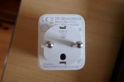
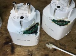
Here you can see my smart plug glued back together - the marks make it obvious, where I had to use force...
Step 2 - Prepare for Flashing
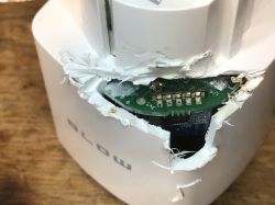
Once the device has been opened, you should easily find the blue board labeled "WB2S" - this is the one you need to flash. Regretfully the pins required to do an UART flash are not accessible at all. Neither is it possible to desolder the board, unless you desolder the main PCB first. I opted against that option, because I did not want to mess with the 220V main electricity circuitry - anything going wrong here and your device might catch fire or you might catch an electric shock, once you plug it back in. Compared to that, messing with the 3.3V BK7231T IC is relatively safe (or so do I hope).
Luckily, there is another, less used but still viable option to flash your device: SPI. And just a lucky, the pins for that are quite accessible. At least most of them. Once I had everything soldered together according to that diagram, I figured that the 3.3V power supply had been omitted. Therefore I give you the complete wiring instructions here:
CEN -> GPIO22
SCK -> SPI0 SCLK
CSN -> SPI0 CE0
SI -> SPI0 MOSI
(ADC_)SO -> SPI0 MISO
VBAT -> 3v3
GND -> Ground
For you reference:
WB2S Datasheet
Raspberry Pi Pinout
You will notice that especially the VBAT and GND pads are really difficult to solder to, because the main PCB is in the way. Consequently (after I barely managed to solder the VBAT pad) I cheated a little and connected the Ground via other means: It turns out that the metal case, protecting the actual IC, is grounded as well
I wish you the best of luck with soldering!
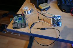
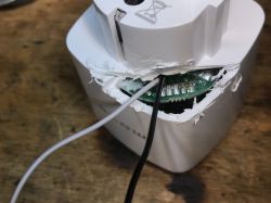
My initial attempt with only four wires. VBAT and GND are still missing.
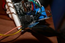
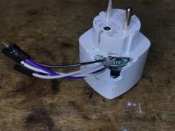
And the final version with all six wires connected. If you can't see yourself soldering in the tiny gap here, this instruction is probably not for you.
Step 3 - Make a backup
If you managed to get until here, the difficult part is over now (unless you are good with hardware and really bad with software).
However, you still have to test, where your soldering attempts were actually successful or whether you have to try again. This is easily done by running the hid_download_py utility to create a dump/backup of your devices flash memory.
This will dump the flash memory, starting from address 0x0 and up to 0x12A000. You might want to dump more than that but since this portion contains the original bootloader and firmware, there is no real need to.
If everything has been wired up correctly, the read process should start after a few seconds. If not, then something is not connected quite right. Sorry.
Step 4 - Disable write protection
This step was a bit difficult to figure out, since it was not documented anywhere. Apparently most manufactures do not bother to enable write protection, so the flashing process will work in most cases - however, not in my case. Luckily, removing the write protection turned out to be quite easy, once I had seen trough the relevant parts of the flash memory data sheet.
The following python script should do:
Most of this script is just initialization or debug output, the only interesting part is spi.xfer2([0x01, 0x00]), which sets the status register to 0 and therefore disables write protection.
Step 5 - Flashing
Finally! Make sure that you have the right version of OpenBK. The platform in our case should be the BK7231T. At least that's the chip one build into the WB2S module. However, manufacturers of cheap smart devices are known to regularly sell product versions with different chips under the same name, so make sure that your module is actually the WB2S. Regarding the usage: We will do a SPI Flash. Taken together, this means that you will want to download OpenBK7231T_QIO_X.XX.XXX.bin.
Once downloaded, you can flash with the following command:
To my understanding, the UART version is the same just without bootloader, so if you leave out the -s 0 flag, you should be able use that version instead. However, this is just a theory and I did not actually try this. The good news: If you want to try and brick your device, chances are good, that you can recover from it easily. While UART does break, if you flash the wrong bootloader, SPI won't
Step 6 - Basic Configuration
After the flashing is done, your device should be restarted automatically and will start blinking twice per second. This indicates that the device is now in Access Point mode and you can connect to it from your computer or smartphone. The AP SSID should start with OpenBK7231T so it will be easy to spot. Connect to it and open http://192.168.4.1/index.
The first thing to setup is usually your own WiFi - when this is done, you probably want to configure the device hardware: LED, Button, Relay and Power Sensor (BL0937CF1). For that you can use the following config:
That's it, your done! Congratulations! There is still some more configuration work to do of course, but what exactly you want from here on is up to you.
Please leave a comment, if you managed to get everything working - or if something did not work out for you, so that I can fix my instructions.
Also I would be interested to know, whether you can get the power sensor to work: I was able to calibrate Voltage and Watt readings, but the Ampere reading is inversed / random / definitely not right.
in this topic I'll explain to you, how you can flash OpenBeken (a.k.a. OpenBK7231T) to a LEDVANCE Smart+ (a.k.a. Smart WiFi Plug AC28208).

Personally I would estimate, that the difficulty of flashing OpenBeken to this device is rather high compared to other smart plugs, so you might want to reconsider. Anyway, make sure to read this post completely before you start and make sure that you understand all steps of this instruction and know how to perform them - I do assume at least some basic soldering & programming knowledge from your side!
Be sure that you have the following materials available, ideally before you start. Otherwise you might find yourself with a half-disassembled device and have to get creative, because you are missing some hardware, software, etc. I know, what I am talking about here...
Materials
* Cutter knife & spudger for opening
* Raspberry Pi, or similar Linux device with SPI interface
-> Must be able to run hid_download_py
-> And of course you also need a recent version of OpenBeken
* Soldering station with a fine tip, solder, maybe flux
* Six jumper wires with one end to solder and the other end to plug onto your Raspberry Pi pin header
Step 1 - Open
To open the device you will need to use a cutter knife, some force and a lot of time. Turn the device upside down and you will see where the two pieces of the housing have been glued together. You should use your cutter knife to separate both on all four sides and if possible in the corners as well. Once this is done, use your spudger (or your cutter knife as well, if you are adventurous) to pry open each side. Just a little will be enough but especially the corners can be quite difficult to separate.

Here you can see my smart plug glued back together - the marks make it obvious, where I had to use force...
Step 2 - Prepare for Flashing
Once the device has been opened, you should easily find the blue board labeled "WB2S" - this is the one you need to flash. Regretfully the pins required to do an UART flash are not accessible at all. Neither is it possible to desolder the board, unless you desolder the main PCB first. I opted against that option, because I did not want to mess with the 220V main electricity circuitry - anything going wrong here and your device might catch fire or you might catch an electric shock, once you plug it back in. Compared to that, messing with the 3.3V BK7231T IC is relatively safe (or so do I hope).
Luckily, there is another, less used but still viable option to flash your device: SPI. And just a lucky, the pins for that are quite accessible. At least most of them. Once I had everything soldered together according to that diagram, I figured that the 3.3V power supply had been omitted. Therefore I give you the complete wiring instructions here:
CEN -> GPIO22
SCK -> SPI0 SCLK
CSN -> SPI0 CE0
SI -> SPI0 MOSI
(ADC_)SO -> SPI0 MISO
VBAT -> 3v3
GND -> Ground
For you reference:
WB2S Datasheet
Raspberry Pi Pinout
You will notice that especially the VBAT and GND pads are really difficult to solder to, because the main PCB is in the way. Consequently (after I barely managed to solder the VBAT pad) I cheated a little and connected the Ground via other means: It turns out that the metal case, protecting the actual IC, is grounded as well
I wish you the best of luck with soldering!

My initial attempt with only four wires. VBAT and GND are still missing.

And the final version with all six wires connected. If you can't see yourself soldering in the tiny gap here, this instruction is probably not for you.
Step 3 - Make a backup
If you managed to get until here, the difficult part is over now (unless you are good with hardware and really bad with software).
However, you still have to test, where your soldering attempts were actually successful or whether you have to try again. This is easily done by running the hid_download_py utility to create a dump/backup of your devices flash memory.
./spigrogram -r -s 0 -l 12A000This will dump the flash memory, starting from address 0x0 and up to 0x12A000. You might want to dump more than that but since this portion contains the original bootloader and firmware, there is no real need to.
If everything has been wired up correctly, the read process should start after a few seconds. If not, then something is not connected quite right. Sorry.
Step 4 - Disable write protection
This step was a bit difficult to figure out, since it was not documented anywhere. Apparently most manufactures do not bother to enable write protection, so the flashing process will work in most cases - however, not in my case. Luckily, removing the write protection turned out to be quite easy, once I had seen trough the relevant parts of the flash memory data sheet.
The following python script should do:
from spidev import SpiDev
from RPi import GPIO
from time import sleep
GPIO.setmode(GPIO.BCM)
GPIO.setup(22, GPIO.OUT)
spi = SpiDev()
spi.open(0, 0)
spi.mode = 3
spi.max_speed_hz = 50000
GPIO.output(22, GPIO.LOW)
sleep(1)
GPIO.output(22, GPIO.HIGH)
spi.xfer2([0xD2]*250)
[_, reg_prev] = spi.xfer2([0x05, 0x00])
spi.xfer2([0x01, 0x00])
[_, reg_after] = spi.xfer2([0x05, 0x00])
print("Status register overwritten: Was {0}, now {1}".format(reg_prev, reg_after))
Most of this script is just initialization or debug output, the only interesting part is spi.xfer2([0x01, 0x00]), which sets the status register to 0 and therefore disables write protection.
Step 5 - Flashing
Finally! Make sure that you have the right version of OpenBK. The platform in our case should be the BK7231T. At least that's the chip one build into the WB2S module. However, manufacturers of cheap smart devices are known to regularly sell product versions with different chips under the same name, so make sure that your module is actually the WB2S. Regarding the usage: We will do a SPI Flash. Taken together, this means that you will want to download OpenBK7231T_QIO_X.XX.XXX.bin.
Once downloaded, you can flash with the following command:
./spigrogram -w -s 0 OpenBK7231T_QIO_X.XX.XXX.binTo my understanding, the UART version is the same just without bootloader, so if you leave out the -s 0 flag, you should be able use that version instead. However, this is just a theory and I did not actually try this. The good news: If you want to try and brick your device, chances are good, that you can recover from it easily. While UART does break, if you flash the wrong bootloader, SPI won't
Step 6 - Basic Configuration
After the flashing is done, your device should be restarted automatically and will start blinking twice per second. This indicates that the device is now in Access Point mode and you can connect to it from your computer or smartphone. The AP SSID should start with OpenBK7231T so it will be easy to spot. Connect to it and open http://192.168.4.1/index.
The first thing to setup is usually your own WiFi - when this is done, you probably want to configure the device hardware: LED, Button, Relay and Power Sensor (BL0937CF1). For that you can use the following config:
{
  "vendor": "LEDVANCE",
  "bDetailed": "0",
  "name": "LEDVANCE Smart+",
  "model": "Smart WiFi Plug AC28208",
  "chip": "BK7231T",
  "board": "WB2S",
  "pins": {
    "6": "Btn;0",
    "7": "BL0937CF;0",
    "8": "BL0937CF1;0",
    "10": "LED_n;0",
    "24": "Rel;0",
    "26": "BL0937SEL;0"
  }
}
That's it, your done! Congratulations! There is still some more configuration work to do of course, but what exactly you want from here on is up to you.
Please leave a comment, if you managed to get everything working - or if something did not work out for you, so that I can fix my instructions.
Also I would be interested to know, whether you can get the power sensor to work: I was able to calibrate Voltage and Watt readings, but the Ampere reading is inversed / random / definitely not right.
Cool? Ranking DIY


