logo elektroda
logo elektroda
X
logo elektroda

[CB2S/BK7231N] Double relay module with additional buzzer Woox R7279

p.kaczmarek2 1650 2
ADVERTISEMENT
Treść została przetłumaczona polish » english Zobacz oryginalną wersję tematu
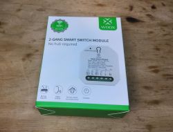
  • Packaging of the Woox R7279 relay module with WiFi.
    Here I will present a double relay module, which is distinguished by the fact that it also has a buzzer on board, which can be used for various types of automation requiring sound signaling of a given device status. I will show its interior, describe the process of changing the firmware and describe its GPIO role.

    Purchase Woox R7279
    The product can be purchased in our country for PLN 70:
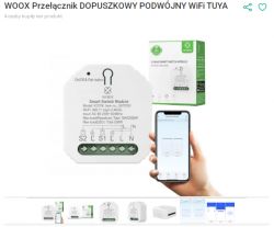
    Woox R7279 dual relay module with smartphone app
    Already in the offer description we can read that R7279 is an improved version of R4967:
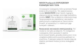
    Packaging and description of the Woox R7279, a dual in-wall WiFi relay module.
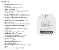
    Specification:
    Woox R7279 module with technical specifications.
    R7279 works with the Woox application, but here I will show you how to change its firmware.
    This is what we get in practice:
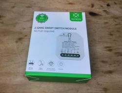
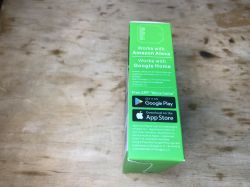
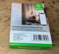
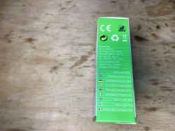
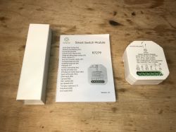
    Packaging of the Woox R7279 dual relay module Side of the Woox R7279 module packaging with Google Play and App Store apps. Woox R7279 module packaging with information about no subscription required. Side of the Woox R7279 module box with technical data. Woox R7279 relay module with instruction and packaging
    Interestingly, there is a code on the packaging: 2972791.
    Instruction:
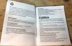
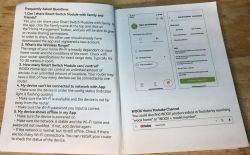
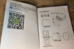
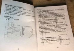
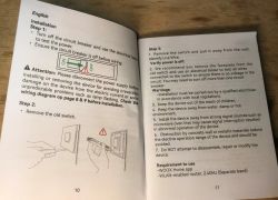
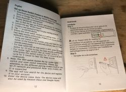
    User manual for Woox R7279 product with technical information. Page from Woox module manual with FAQ section and app illustration. Woox R7279 module manual with QR code and connection diagram Installation manual for Woox R7279 relay module with wiring diagram. Open installation instructions for the Woox R7279 module. Setup instructions for the Woox Home module in English and Dutch
    The instructions include a QR code with a link to the Woox application.

    R7279 interior
    Normally, you just need to pry the casing off. There are no screws.
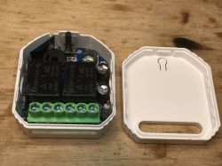
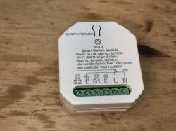
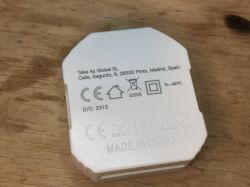
    Interior of the Woox R7279 relay module with buzzer White Woox R7279 module with markings on the casing. Back of Woox R7279 module with manufacturer labels and certifications.
    At first everything looks standard:
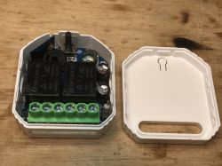
    Interior of Woox R7279 relay module with buzzer
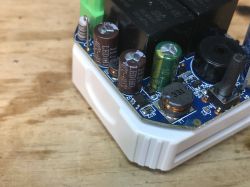
    The input has a fuse resistor and a filter with two electrolytic capacitors and a choke:
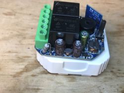
    Interior of the Woox R7279 relay module with a buzzer.
    The power supply is non-isolated and based on BP2525 as usual:
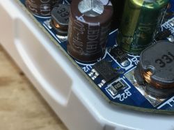
    Close-up of internal components of Woox R7279 relay module Section of the Woox R7279 relay module interior with visible electronic components.
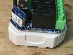
    But inside, apart from two relays and a WiFi module, there is also a buzzer:
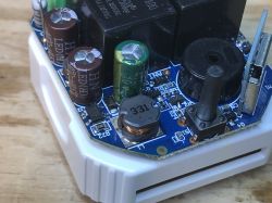
    View of the interior of relay module R7279 with electronic components.
    The WiFi module itself is CB2S, i.e. BK7231N:
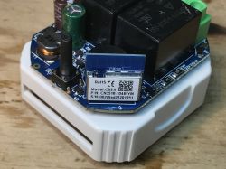
    Interior of Woox R7279 relay module with visible CB2S module. Interior of the Woox R7279 dual relay module with a buzzer.
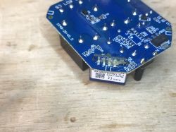
    At the bottom of the PCB there is a 3.3V LDO and a place that I suspect is intended for an energy measurement system (BL0942, maybe?):
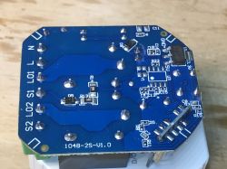
    Close-up view of the PCB board of the Woox R7279 relay module.

    Firmware change
    I loaded OpenBeken:
    https://github.com/openshwprojects/OpenBK7231T_App
    via bk7231tool flasher:
    https://github.com/openshwprojects/BK7231GUIFlashTool
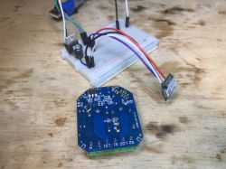
    I desoldered the entire CB2S:
    Close-up of the internal part of the Woox R7279 relay module on a blue PCB with visible soldered pins. PCB of the Woox R7279 relay module with a buzzer on a wooden table. Close-up of the bottom part of the Woox R7279 module PCB with visible tracks and electronic components.
    According to the flasher instructions, RX, TX and GND and 3.3V from a good 3.3V LDO were enough. I rebooted by cutting off the power.
    Flasher imported the device configuration:
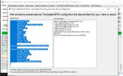
    Screenshot showing the configuration of the Woox R7279 device.
    Here is Tuya's JSON:
    Code: JSON
    Log in, to see the code

    You can see information about what is on which pin, e.g.:
    
    	"buzzer_io":"26",
    

    Verbal description:
    
    Device seems to be using CB2S module, which is BK7231N chip.
    - Relay (channel 1) on P24
    - Relay (channel 2) on P10
    - TglChannelToggle (channel 1) on P8
    - TglChannelToggle (channel 2) on P6
    - Pair/Toggle All Pin on P23
    

    Additionally, the buzzer is on P26.

    OBK template:
    Code: JSON
    Log in, to see the code


    Summary
    The module is quite expensive, although it is distinguished by the presence of the already mentioned buzzer. At the moment, the Tuya configuration decoder does not even automatically detect this buzzer, you have to manually look for the keys buzzer_io and buzzer_pwm but this will probably change soon, I will just update the flasher and importer.
    Apart from that - no problems.
    It is also possible that the whole thing could be flashed into the system, but I preferred to desolder the CB2S, it's not a problem, a little flux and a good braid are enough, you can easily remove the old binder and then the module slides out of the board by itself.
    This way we can enjoy another device free from the cloud and operating in a 100% private and local way with Home Assistant.

    Cool? Ranking DIY
    Helpful post? Buy me a coffee.
    About Author
    p.kaczmarek2
    Moderator Smart Home
    Offline 
    p.kaczmarek2 wrote 11966 posts with rating 9996, helped 572 times. Been with us since 2014 year.
  • ADVERTISEMENT
  • #2 20875647
    morgan_flint
    Level 14  
    p.kaczmarek2 wrote:
    At the bottom of the PCB there is a 3.3V LDO and a place that I suspect is intended for an energy measurement system (BL0942, maybe?)

    Hello, @p.kaczmarek2

    I think that IC is for a RF receiver version of the device as it's very similar to the one you can see in the 6th and 7th photos of this post.

    It's a good thing as it allows to connect an extra sensor to P23/ADC3 port easily
  • #3 20875692
    p.kaczmarek2
    Moderator Smart Home
    It seems you may be right. At first I suspected it may be BL0937 but it seems that the GND position, etc, does not match and I can see no place for current measurement resistor. So it's may be an RF IC,after all
    Helpful post? Buy me a coffee.
ADVERTISEMENT