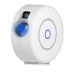
Overview
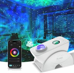
This projector has 5 components
- RGB LED, projected through a lens (nebula)
- Laser, projected through a screen (stars)
- Motor, turns the lense and screen, resulting in movement of the nebula and stars
- Microphone, to sync the light to music
- 3 Buttons on the front, to turn on the projector, cycle scenes, activate music mode
Info:
- Chip: BK7231N
- Module: CBU
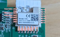
It's quite close to the device showcased here, but it features a different chip, Tuya module and construction, so I figured it would be worth documenting. Nevertheless, most of the work has been done for the Genio projector so it was easy to get this one running. Thanks @joelstevens1101 and @p.kaczmarek2 for your work!
Teardown
Remove the 4 screws at the bottom of the device. They are quite hard to reach, you need a very short phillips head screwdriver.
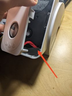
Lift off the top cover to right hand side. Caution: The button board is connected with the main board, so you need to unplug the red cable before removing the cover completely.
Remove 6 more screws from the black middle frame.
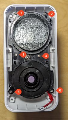
Remove the lense and the screen. The motor is attached to the frame on the bottom. When moving the frame make sure you don't damage the cables. Either put the frame to the side or unplug the cable with pliers.
The main board is glued in place. I had to wiggle it for some time with moderate force to get it out. When pulling out the board, again pay attention to the cables.
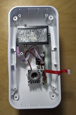
Unplug the rest of the cables. They are also glued to the connectors, so make sure you pull on the plug, not on the cables.
You did it! The board looks like this:
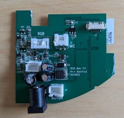
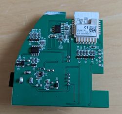
Flashing
For VCC and GND I used the pads below the module, as they are easier to solder to. They are labelled. TX (Pin 15) and RX (Pin 16) are on the right hand side of the chip. Tin your wires and pads, flux will help you. To solder, just connect the wire with the pad and touch it with the iron briefly.
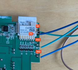
Connect the soldered wires to your programmer. I used a NodeMCU that I had lying around as described here. Conveniently it also operates on 3.3V so I had no issue with voltage conversion.
The BK7231 GUI Flash Tool works just fine for flashing. It is quite straightforward: Make sure you select the correct COM port and BK7231N as the chip. Start the backup and flashing procedure and power cycle the chip when prompted. Note: Only reset the chip, not the programmer. You can find the backup of my devices ROM attached to this thread.
Should you not able be able to get a connection to in the flash tool, double check your solder joints. The ones on the chip in my picture actually short TX and RX, so I had to redo them.
After flashing is complete, power cycle the device again. A new Wifi network should appear. Set up the device to join your local network. Confirm you can connect the device to it using your Wifi.
Congrats! That was the hard part - the new firmware is flashed. You can now desolder the wires you used for flashing and put the device back together.
Setup
Launch the webapp and head to Import. Paste the template in the first column and click Clear OBK and apply new script from above.
After restarting, on the main page you should be already able to control the RGB LED. But we are not done yet.
To get the motor and laser working head over to Filesystem, click Create File, confirm autoexec.bat as the name and paste the following content into it. It will couple the state of the of the LED to the motor and laser and set startup values for them.
Confirm with Save, Reset SVM and run file as script thread.
Now the main menu should look like this:
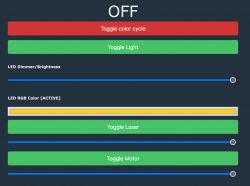
You can toggle the LED, Motor and Laser and control the brightness and speed. Also there is a button to automatically cycle the colors. The color pallete can be customized at the bottom of the script.
Buttons
The buttons are configured like this
- Music: 1x Click: toggle laser, 2x Click: toggle motor
- Switch: 1x Click: toggle LED + laser + motor, 2x Click: next color, Hold: change brightness
- Scene: Toggle automatic color palette cycle
Homeassistant
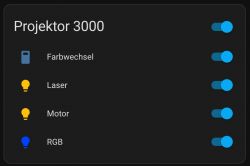
This config adds the light, motor, rgb and the color cycle mode to Homeassistant. You will need to adjust the mqtt topics to match your configuration.
What doesn't work
Microphone
The projector has a builtin piezo microphone to sync the light to music. I wasn't able to get that working. I assume it's connected to PIN 5 (ADC) but I can't tell if the readings correlate to the music.


This projector has 5 components
- RGB LED, projected through a lens (nebula)
- Laser, projected through a screen (stars)
- Motor, turns the lense and screen, resulting in movement of the nebula and stars
- Microphone, to sync the light to music
- 3 Buttons on the front, to turn on the projector, cycle scenes, activate music mode
Info:
- Chip: BK7231N
- Module: CBU

It's quite close to the device showcased here, but it features a different chip, Tuya module and construction, so I figured it would be worth documenting. Nevertheless, most of the work has been done for the Genio projector so it was easy to get this one running. Thanks @joelstevens1101 and @p.kaczmarek2 for your work!
Teardown
Remove the 4 screws at the bottom of the device. They are quite hard to reach, you need a very short phillips head screwdriver.
Lift off the top cover to right hand side. Caution: The button board is connected with the main board, so you need to unplug the red cable before removing the cover completely.

Remove 6 more screws from the black middle frame.

Remove the lense and the screen. The motor is attached to the frame on the bottom. When moving the frame make sure you don't damage the cables. Either put the frame to the side or unplug the cable with pliers.
The main board is glued in place. I had to wiggle it for some time with moderate force to get it out. When pulling out the board, again pay attention to the cables.

Unplug the rest of the cables. They are also glued to the connectors, so make sure you pull on the plug, not on the cables.
You did it! The board looks like this:


Flashing
For VCC and GND I used the pads below the module, as they are easier to solder to. They are labelled. TX (Pin 15) and RX (Pin 16) are on the right hand side of the chip. Tin your wires and pads, flux will help you. To solder, just connect the wire with the pad and touch it with the iron briefly.

Connect the soldered wires to your programmer. I used a NodeMCU that I had lying around as described here. Conveniently it also operates on 3.3V so I had no issue with voltage conversion.
The BK7231 GUI Flash Tool works just fine for flashing. It is quite straightforward: Make sure you select the correct COM port and BK7231N as the chip. Start the backup and flashing procedure and power cycle the chip when prompted. Note: Only reset the chip, not the programmer. You can find the backup of my devices ROM attached to this thread.
Should you not able be able to get a connection to in the flash tool, double check your solder joints. The ones on the chip in my picture actually short TX and RX, so I had to redo them.
After flashing is complete, power cycle the device again. A new Wifi network should appear. Set up the device to join your local network. Confirm you can connect the device to it using your Wifi.
Congrats! That was the hard part - the new firmware is flashed. You can now desolder the wires you used for flashing and put the device back together.
Setup
Launch the webapp and head to Import. Paste the template in the first column and click Clear OBK and apply new script from above.
{
  "vendor": "Generic",
  "bDetailed": "0",
  "name": "Smart LED Galaxy Projector",
  "model": "SK26",
  "chip": "BK7231N",
  "board": "CBU",
  "flags": "1446912",
  "keywords": [
    "led",
    "rgb",
    "star",
    "nebula",
    "projector",
    "laser",
    "motor"
  ],
  "pins": {
    "6": "PWM_n;3",
    "7": "PWM;5",
    "8": "PWM;4",
    "14": "Btn_SmartLED;0",
    "20": "Btn_ScriptOnly;0",
    "22": "Btn_ScriptOnly;0",
    "24": "PWM_n;2",
    "26": "PWM_n;1"
  },
  "command": "",
  "image": "https://obrazki.elektroda.pl/2917649700_1702586359.jpg",
  "wiki": "https://www.elektroda.com/rtvforum/viewtopic.php?p=20863828#20863828"
}
After restarting, on the main page you should be already able to control the RGB LED. But we are not done yet.
To get the motor and laser working head over to Filesystem, click Create File, confirm autoexec.bat as the name and paste the following content into it. It will couple the state of the of the LED to the motor and laser and set startup values for them.
// PWM TOGGLER SETUP

// enable toggler driver
startDriver PWMToggler

// toggler slot one is the laser, channel 4
toggler_channel0 4
toggler_name0 Laser

// toggler slot two is the motor, channel 5
toggler_channel1 5
toggler_name1 Motor

// set startup values for laser
toggler_set0 100
toggler_enable0 1

// set startup values for motor
toggler_set1 100
toggler_enable1 1

// LED, LASER, MOTOR COUPLING

// when disabling the LED, also disable laser and motor
addEventHandler LEDState 0 backlog toggler_enable0 0; toggler_enable1 0;

// when enabling the LED, also enable laser and motor
addEventHandler LEDState 1 backlog toggler_enable0 1; toggler_enable1 1;

// BUTTONS

// TOGGLE LASER
alias enable_laser toggler_enable0 1
alias disable_laser toggler_enable0 0

addEventHandler OnClick 20 if $CH4==100 then disable_laser else enable_laser

// TOGGLE MOTOR
alias enable_motor toggler_enable1 1
alias disable_motor toggler_enable1 0

addEventHandler OnDblClick 20 if $CH5==100 then disable_motor else enable_motor

// CYCLE FEATURE
setChannelType 10 Toggle
setChannelLabel 10 "color cycle" 0

alias add_color_cycle_event addRepeatingEventID 10 -1 420 led_nextcolor
alias remove_color_cycle_event cancelRepeatingEvent 420

addChangeHandler Channel10 == 1 add_color_cycle_event
addChangeHandler Channel10 == 0 remove_color_cycle_event

alias enable_color_cycle SetChannel 10 1
alias disable_color_cycle SetChannel 10 0

addEventHandler OnClick 22 if $CH10==1 then disable_color_cycle else enable_color_cycle
addEventHandler LEDState 0 disable_color_cycle

// COLOR PALETTE
SPC 0 FF00AE
SPC 1 BB00FF
SPC 2 5500FF
SPC 3 0008FF
SPC 4 0040FF
SPC 5 0D6CD2
SPC 6 17D1FF
SPC 7 1EFF30
SPC 8 FCD023
SPC 9 FC8F00
SPC 10 FF0000
SPC 11 FF0088
SPC 12 FF00DD
Confirm with Save, Reset SVM and run file as script thread.
Now the main menu should look like this:

You can toggle the LED, Motor and Laser and control the brightness and speed. Also there is a button to automatically cycle the colors. The color pallete can be customized at the bottom of the script.
Buttons
The buttons are configured like this
- Music: 1x Click: toggle laser, 2x Click: toggle motor
- Switch: 1x Click: toggle LED + laser + motor, 2x Click: next color, Hold: change brightness
- Scene: Toggle automatic color palette cycle
Homeassistant
This config adds the light, motor, rgb and the color cycle mode to Homeassistant. You will need to adjust the mqtt topics to match your configuration.

mqtt:
  light:

    - unique_id: "star_projector_rgb"
      name: "RGB"
      availability_topic: "home/living-room/star-projector/connected"

      device:
        name: "Star Projector"
        model: "SK26"
        manufacturer: "Tuya"
        identifiers: "sk26affe"

      # on / off
      state_topic: "home/living-room/star-projector/led_enableAll/get"
      command_topic: "cmnd/home/living-room/star-projector/led_enableAll"
      payload_on: 1
      payload_off: 0

      # rgb
      rgb_state_topic: "home/living-room/star-projector/led_basecolor_rgb/get"
      rgb_value_template: "{{ value[0:2]|int(base=16) }},{{ value[2:4]|int(base=16) }},{{ value[4:6]|int(base=16) }}"
      rgb_command_topic: "cmnd/home/living-room/star-projector/led_basecolor_rgb"
      rgb_command_template: "{{ '#%02x%02x%02x0000' | format(red, green, blue)}}"

      # brightness
      brightness_command_topic: "cmnd/home/living-room/star-projector/led_dimmer"
      brightness_state_topic: "home/living-room/star-projector/led_dimmer/get"
      brightness_scale: 100

    - unique_id: "star_projector_laser"
      name: "Laser"

      state_topic: "home/living-room/star-projector/toggler_enable0/get"
      command_topic: "cmnd/home/living-room/star-projector/toggler_enable0"
      payload_on: 1
      payload_off: 0

      brightness_state_topic: "home/living-room/star-projector/toggler_set0/get"
      brightness_value_template: "{{value}}"
      brightness_command_topic: "cmnd/home/living-room/star-projector/toggler_set0"
      brightness_scale: 100

      device:
        identifiers: "sk26affe"

    - unique_id: "star_projector_motor"
      name: "Motor"

      state_topic: "home/living-room/star-projector/toggler_enable1/get"
      command_topic: "cmnd/home/living-room/star-projector/toggler_enable1"
      payload_on: 1
      payload_off: 0

      brightness_state_topic: "home/living-room/star-projector/toggler_set1/get"
      brightness_value_template: "{{value}}"
      brightness_command_topic: "cmnd/home/living-room/star-projector/toggler_set1"
      brightness_scale: 100

      device:
        identifiers: "sk26affe"

  switch:

    - unique_id: "star_projector_color_cycle"
      name: "Color cycle"

      state_topic: "home/living-room/star-projector/10/get"
      command_topic: "home/living-room/star-projector/10/set"
      payload_on: 1
      payload_off: 0

      device:
        identifiers: "sk26affe"
What doesn't work
Microphone
The projector has a builtin piezo microphone to sync the light to music. I wasn't able to get that working. I assume it's connected to PIN 5 (ADC) but I can't tell if the readings correlate to the music.
Cool? Ranking DIY


