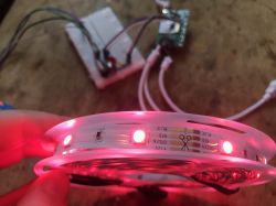
Here I will show the floashing procedure of RGB LED strip controller. As usual, I will start with a teardown, and then change its firmware to OpenBeken . I will also provide its template here, i.e. a description of the roles of its GPIO, which PWMs are used, etc. Finally, I will link few video tutorials showing what can be done next with a LED strip controller programmed in this way.
Purchasing Appio Strip 7331
The product is advertised as a multi-colored IRM 36W 15M LED strip. Sometimes the phrase "double" is also mentioned there, but you can`t set two colors at once, it`s one RGB strip controller with two strip plugs. The whole thing can be purchased for just over PLN 100, below is a screenshot of the offer:
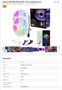
Fragment of the description:
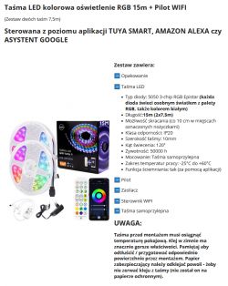
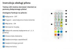
Remote Control Features:
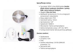
Specification and contents of the set:
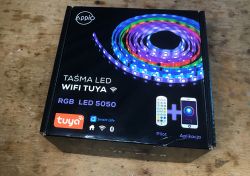
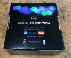
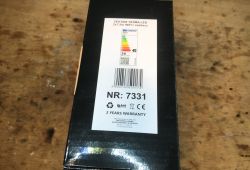
Now let`s see what we get in practice. Packaging and markings:
The contents of the set... not bad, there`s even a power supply:
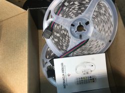
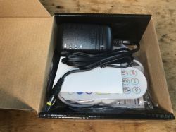
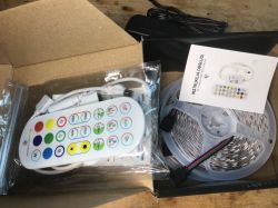

Instruction:
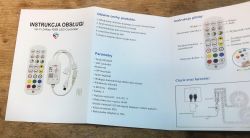
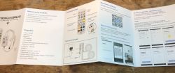



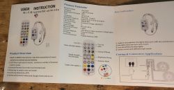
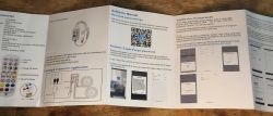
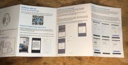
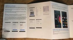

The inscription WiFi+Bluetooth itself suggests that this is not a product based on ESP8266 ...
The manual mentions the WX300P model, which would indicate this product , but the interior is slightly different...
The interior of Appio Strip 7331
And here is our controller:
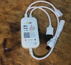
We remove the cover (just pry it off):
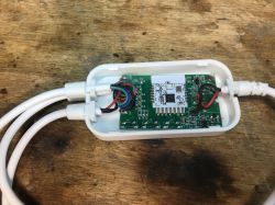
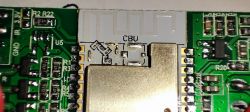
Inside there is a CBU module, known for having the BK7231N on board, but here it is in the BL2028N version:
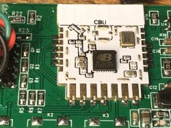
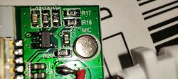
Here you can see a microphone, probably connected to P23 from BK, i.e. ADC:
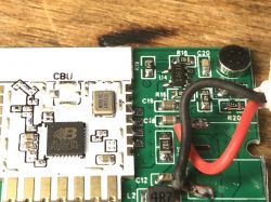
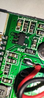
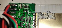
Below you can see the step down converter, can anyone decipher the GBF20 marking? It converts 12V from the belt into 3.3V for the WiFi module:
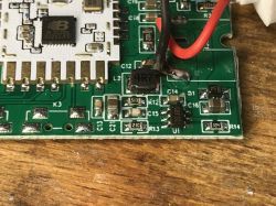
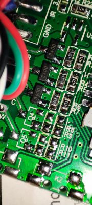
You can also see the space for buttons on the PCB:
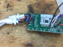
And here we have transistors, this is the RGB strip, i.e. three colors:
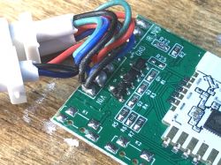
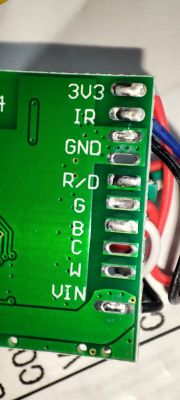
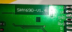
The bottom of the PCB is quite poor:
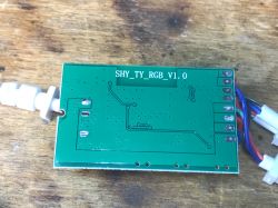
Designation: SHY_TY_RGB_V1.0.
Appio Strip 7331 firmware change
According to CBU documentation:
https://developer.tuya.com/en/docs/iot/cbu-module-datasheet?id=Ka07pykl5dk4u
and flasher instructions:
https://github.com/openshwprojects/BK7231GUIFlashTool
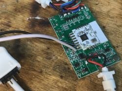
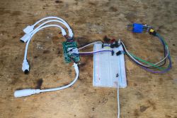
We solder four wires, ground, 3.3V, RX and TX. We copy a 2MB copy of the batch and then upload the OBK with flasher:
OBK template:
Code: JSON
Short test of OBK operation:
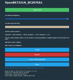
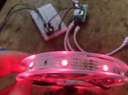
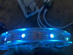
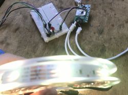
Everything works. You can also script the buttons, for example according to this tutorial:
You can add a button (physical):
You can also connect to other devices via Tasmota DGR:
And of course pair with HA:
The possibilities are great.
Summary
It`s supposed to be a double controller, but in fact both strips are connected to the same outputs, so we won`t choose different colors. Apart from that - no complaints, although it`s a pity that they didn`t remove the buttons with space for the PCB. In my opinion, such a product without "physical" control should not exist, but fortunately, after changing the firmware, it can be easily "repaired" and restore the missing buttons. I think that after changing the firmware, this controller may even find its place in our home, although I wouldn`t expect it to drive long strips, looking at these tiny MOSFETs at the output...
Cool? Ranking DIY Helpful post? Buy me a coffee.


