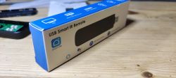
This product caught my attention on Ali Express a few days ago. It had the familiar Tuya/Smart Life/2.4G-wifi only kind of vibe about it that might mean it's a Beken-based device. And indeed it was!

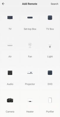
To begin, I plugged it into a standard USB port and paired it with the Tuya app just to see what firmware version it had and to see what remote control options were available.

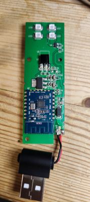
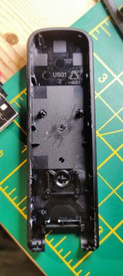
Using my metal spudger I pried open the case from the USB hinge and slowly around the edge. There is a small amount of glue as well as some clips along the entire edge. I was a little rough at the beginning and broke one of the shoulders off. No matter. Slow and steady is the key.
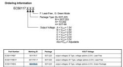
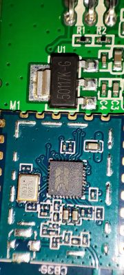
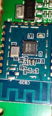
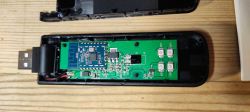
As soon as the chassis is open, a shiny CB3S greets you. Below that is the 50117K-G E-CMOS 5V-3.3V voltage regulator, presumably to drop the 5V of USB down to 3.3 for the BK7231N on the CB3S.
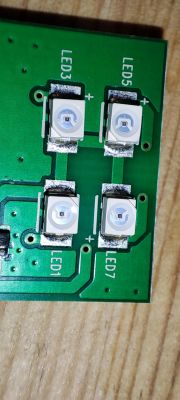
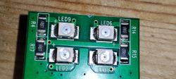
I assumed the central IR component, as there is only one of them, was for programming remote control commands the Tuya app may not cater for. I guess the expectation is that this would be used less often and the user would expect to point their remote directly at the unit. In opposition to the receive, the IR send LEDs are a family of 8, 4 on both sides of the PCB. I guess this is because the user expects this device to work almost omnidirectionally, not having to worry too much where the unit is placed
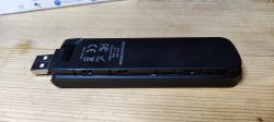
The rear of the PCB has some very helpful GND, 3V3, RX1 and TX1 pads, from which I was able to flash OpenBK firmware using the Easy BK Flasher GUI.
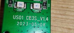
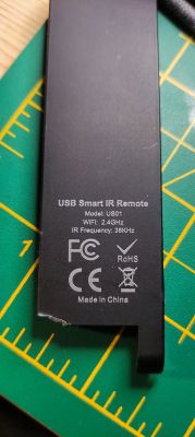
silkscreen text for forum searchers: US01 CB3S_V1.4 2023-05-08
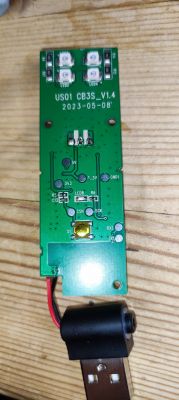
I did not unsolder any parts nor cut any traces to be able to flash. I used pogo pins, USB-TTL adaptor and an external 3.3v power supply, though the 5V from a USB would have worked too.
Before flashing I used the TXD2, GND and 3V3 pins on the front of the CB3S to pull the UART boot log, attached.
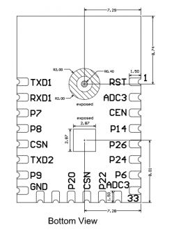
Unfortunately BK flasher could not determine the GPIO assignments so I used trial and error to find the btn and the LED. I used a multimeter to find that the ir_rec data leg went to p7.
p8 led (or wifi led?)
p6 btn
p7 ir_rec
I've yet to determine the ir_send GPIO (I assume it's one GPIO because all the sending LEDs would be sending the same signal in unison) because I can't seem to be able to nail the command to simulate a send. I've received the following on/off button code from a hi-fi remote control
but setting undetermined GPIOs to IRSend mode, rebooting and trying manual commands of this nature
and others I've found on the forum that are noted as valid, like
all fail with

The IR driver is running, so not sure what's wrong yet.
OBK template for this device

To begin, I plugged it into a standard USB port and paired it with the Tuya app just to see what firmware version it had and to see what remote control options were available.


Using my metal spudger I pried open the case from the USB hinge and slowly around the edge. There is a small amount of glue as well as some clips along the entire edge. I was a little rough at the beginning and broke one of the shoulders off. No matter. Slow and steady is the key.
As soon as the chassis is open, a shiny CB3S greets you. Below that is the 50117K-G E-CMOS 5V-3.3V voltage regulator, presumably to drop the 5V of USB down to 3.3 for the BK7231N on the CB3S.

I assumed the central IR component, as there is only one of them, was for programming remote control commands the Tuya app may not cater for. I guess the expectation is that this would be used less often and the user would expect to point their remote directly at the unit. In opposition to the receive, the IR send LEDs are a family of 8, 4 on both sides of the PCB. I guess this is because the user expects this device to work almost omnidirectionally, not having to worry too much where the unit is placed


The rear of the PCB has some very helpful GND, 3V3, RX1 and TX1 pads, from which I was able to flash OpenBK firmware using the Easy BK Flasher GUI.
silkscreen text for forum searchers: US01 CB3S_V1.4 2023-05-08

I did not unsolder any parts nor cut any traces to be able to flash. I used pogo pins, USB-TTL adaptor and an external 3.3v power supply, though the 5V from a USB would have worked too.
Before flashing I used the TXD2, GND and 3V3 pins on the front of the CB3S to pull the UART boot log, attached.
ADVERTISEMENT

Unfortunately BK flasher could not determine the GPIO assignments so I used trial and error to find the btn and the LED. I used a multimeter to find that the ir_rec data leg went to p7.
Sorry, no meaningful pins data found. This device may be TuyaMCU or a custom one with no Tuya config data.
No module information found.
And the Tuya section starts, as usual, at 2023424
p8 led (or wifi led?)
p6 btn
p7 ir_rec
{
	"reset_pin":"6",
	"wfst_pin":"8",
	"owm":"1",
	"reset_lv":"0",
	"rsthold":"3",
	"wfst_lv":"1",
	"netyc":"1",
	"infrr":"7",
	"netnc":"0",
	"infre":"26",
	"crc":"42",
	"}ac_pin":"chs8um6esddtzco1hbAgw_di{abi",
	"id":"null",
	"swv":"2.0.0",
	"bv":"40.00",
	"pv":"2.2",
	"lpv":"3.3",
	"pk":"key54vrth5askhsj",
	"firmk":"key54vrth5askhsj",
	"cadv":"1.0.3",
	"cdv":"1.0.0",
	"dev_swv":"2.0.0",
	"s_id":"null",
	"dtp":"0",
	"sync":"0",
	"attr_num":"0",
	"mst_tp_0":"0",
	"mst_ver_0":"null",
	"mst_tp_1":"0",
	"mst_ver_1":"null",
	"mst_tp_2":"0",
	"mst_ver_2":"null",
	"mst_tp_3":"0",
	"mst_ver_3":"null }{nc_tp",
	"ssid":"null",
	"passwd":"null",
	"md":"0",
	"random":"0",
	"wfb64":"1",
	"stat":"0",
	"token":"null",
	"region":"null",
	"reg_key":"null",
	"dns_prio":"03fAwf_start_md3 )Agw_wsm{nc_tp",
	"psk_key":"6FdexlrpU86zRD5G5GjYpwQOxCmq5kXD0Xpn7",
	"auth_key":"dABzIgXAi2bZaudNgg7C8TfPRA2YNfXu",
	"ap_ssid":"SmartLife",
	"ap_passwd":"null",
	"country_code":"null",
	"bt_mac":"null",
	"bt_hid":"null",
	"prod_test":"false",
	"fac_pin":"chs8um6esddtzco1PBgw_aiAtimer_arr",
	"h_ip":"null",
	"hs_url":"null",
	"hs_ip":"null",
	"hs_psk":"null",
	"hs_psk_ip":"null",
	"mqs_url":"null",
	"mqs_{lastFetchTime":"0",
	"cnt":"0}p",
	"ai_sp":"null",
	"ai_sp_ip":"null",
	"mq_psk":"null",
	"mq_psk_ip":"null",
	"time_z":"null",
	"s_time_z":"null",
	"w{uuid":"61000a40b234094d",
	"wx_uuid":"null",
	"dy_tls_m":"0",
	"cloud_cap":"0",
	"psk21_key":"null }0UAtls_ca_cnt00Ais_stride0{abi",
	"property":"{type",
	"maxlen":"3072}",
	"type":"obj}",
	"{mode":"ro",
	"lckey":"'u4J09X~;_S-u)Z9",
	"h_url":"http",
	"mqs_ip":"null",
	"mq_url":"m2.tuyaeu.com",
	"mq_ip":"18.184.31.90",
	"wx_app_id":"null",
	"index":"0};FBastro_timer{timestamp"
}
I've yet to determine the ir_send GPIO (I assume it's one GPIO because all the sending LEDs would be sending the same signal in unison) because I can't seem to be able to nail the command to simulate a send. I've received the following on/off button code from a hi-fi remote control
Info:IR:IR IR_NEC 0x4583 0x11 0 (32 bits)
Info:IR:IR IR_NEC2 0x4583 0x11 1 (32 bits)
but setting undetermined GPIOs to IRSend mode, rebooting and trying manual commands of this nature
IRSend NEC-0x45830x11-0and others I've found on the forum that are noted as valid, like
IRSend Samsung-0xB24D-0x2929-0all fail with
The IR driver is running, so not sure what's wrong yet.
OBK template for this device
Code: JSON


