logo elektroda
logo elektroda
X
logo elektroda

Mini Universal IR Remote M-18 CBU/BK7231N

omelchuk890 3525 7
ADVERTISEMENT
  • Modul CBU, BK7231N
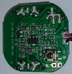
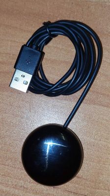
    Device dimensions: diameter 40 mm, thickness 15 mm.
    The power cable is two-core, about 1 m, non-pluggable.
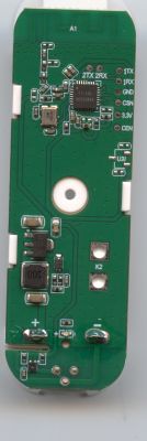
    For firmware - standard procedure, soldered to the pads marked on the board.
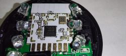
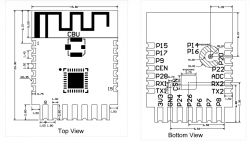
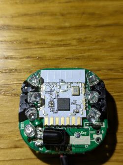
    To reset, the CEN output, soldered the output to gnd, when starting the firmware, I touch the module output directly, because it is problematic to solder, the LED lens is in the immediate vicinity.
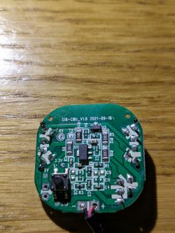
    Matching contacts:
    P8 - IR receiver
    P7 - IR transmitter
    P24 - led
    P26 - button
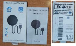
    Purchased here
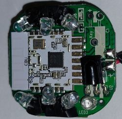
    Mini Universal IR Remote M-18 CBU/BK7231N
    Mini Universal IR Remote M-18 CBU/BK7231N
    Mini Universal IR Remote M-18 CBU/BK7231N
    Mini Universal IR Remote M-18 CBU/BK7231N
    Mini Universal IR Remote M-18 CBU/BK7231N
    Mini Universal IR Remote M-18 CBU/BK7231N

    Cool? Ranking DIY
    About Author
    omelchuk890
    Level 11  
    Offline 
    omelchuk890 wrote 67 posts with rating 9. Been with us since 2022 year.
  • ADVERTISEMENT
  • #2 20326563
    p.kaczmarek2
    Moderator Smart Home
    Good job with flashing that device. I am just wondering, how are you going to use the button?

    Remember that you can easily script it in OpenBeken. It could do everything, you can handle click, onclick, hold, etc events, anyway you want.
    
    addEventHandler OnClick 26 YourCommandHere
    

    You can enter an IRSend here.
    Helpful post? Buy me a coffee.
  • ADVERTISEMENT
  • #3 20327367
    Pawek881
    Level 2  
    hi, i have the same chipset to flash. can you tell me if your points on the rx and tx board are connected to the CBU to tx1/rx2 or tx2/rx2? because I have to connect directly to the CBU.
  • ADVERTISEMENT
  • #4 20327551
    p.kaczmarek2
    Moderator Smart Home
    RX1/TX1 is used for flashing and TX2 is a debug log output
    Helpful post? Buy me a coffee.
  • #5 20327587
    omelchuk890
    Level 11  
    Quote:
    hi, i have the same chipset to flash. can you tell me if your points on the rx and tx board are connected to the CBU to tx1/rx2 or tx2/rx2?

    This is what we need, 1.

    p.kaczmarek2 wrote:
    I am just wondering, how are you going to use the button?

    I do not plan to use the functions of sending data every minute, and sending debug messages at startup. But sometimes, I assume, you will need to connect to the device's web interface, and its IP may be forgotten, lost, etc.
    I plan to send the current IP to the MQTT broker on my devices that have such a button when it is clicked.

    I added a read firmware to the first post, pristine, never turned on.
  • #6 21297552
    sipe
    Level 2  
    Hello all,

    I need help with this device to see if its properly configured or maybe defective.

    I got it flashed with tuya-cloudcutter, then flashed via OTA to version 1.17.767

    My pins configuration are
    "7": "IRSend;0",
    "8": "IRRecv;0",
    "24": "LED;0",
    "26": "Btn;0"

    And everything is working except IRSend. I tried Samsung TV and lamp remote, there is no light output on mobile camera (front or back).

    Button, Wifi LED and IRRecv all works perfectly fine, I can receive IR, toggle wifiled and button press is visible in Logs.

    Triggering in GPIO PIN 7 does not light up LEDs.

    Can someone recommend what to test out? I'm sending simple NEC IRSend which is read fine from device
    Debug:IR:IR decode returned true, protocol 7
    Debug:IR:Address=0x80 Command=0x1
    Debug:IR: Raw-Data=0xFE017F80
    Debug:IR: 32 bits
    Debug:IR: LSB first
    Debug:IR:IR decode returned true, protocol NEC (7)
    Info:IR:IR IR_NEC 0x80 0x1 0 (32 bits)
    Debug:IR:IR fire event took 0ms
    Debug:IR:IR decode returned true, protocol 7
    Debug:IR:Address=0x80 Command=0x1
    Debug:IR:Repeat
    Debug:IR: Gap 40050us
    Debug:IR:IR decode returned true, protocol NEC (7)
    Info:IR:IR IR_NEC 0x80 0x1 1 (0 bits)
    Debug:IR:IR fire event took 0ms

    Info:IR:IR send NEC 0x80 0x1 0 protocol 7 addr 0x80 cmd 0x1 repeats 0 bits override 0

    No light output and no response from lamp.

    Close-up of a circuit board labeled S18-CBU_V1.8 2021-09-16. Electronic circuit board with several LEDs on a wooden surface.
  • ADVERTISEMENT
  • #7 21297597
    p.kaczmarek2
    Moderator Smart Home
    Maybe IR Send LED requires an extra pin to be set to High? How is it connected?
    Helpful post? Buy me a coffee.
  • #8 21297614
    sipe
    Level 2  
    >>21297597

    I'm not sure, everything should be the same as in first post, how I can check how it's connected?

Topic summary

The discussion centers on the Mini Universal IR Remote module M-18 featuring the CBU/BK7231N chipset with dimensions of 40 mm diameter and 15 mm thickness. The device uses a two-core, non-pluggable power cable and requires soldering to specific pads for firmware flashing. Key pin assignments include P8 for IR receiver, P7 for IR transmitter, P24 for LED, and P26 for button input. Users share experiences with flashing the device using standard procedures and tuya-cloudcutter OTA updates. Issues reported include the IRSend function on pin 7 not emitting IR signals despite correct configuration and successful reception on IRRecv. Suggestions include verifying if the IR LED requires an additional pin set to high and clarifying UART connections, where RX1/TX1 is used for flashing and TX2 for debug output. The button can be scripted in OpenBeken firmware to handle various events and send MQTT messages, such as device IP on button press. Troubleshooting involves checking hardware connections and pin configurations to resolve IR transmission problems.
Summary generated by the language model.
ADVERTISEMENT