logo elektroda
logo elektroda
X
logo elektroda

User Experience: Tuya WiFi Smart IR Remote Controller IRC03 [BK7231N] from Aliexpress

atomphil 4962 16
ADVERTISEMENT
  • I bought an IRC03 Universal IR remote control from Aliexpress and would like to share my experience here:
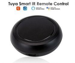
    Tuya Smart IR Remote with compatibility logos.

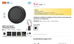
    Tuya Smart IR Remote Control on Aliexpress page.

    https://aliexpress.com/item/1005005942152298.html

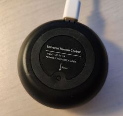
    The device itself is small, very well designed and comes with a USB C cable. It illuminates the room well in all directions with its seven ir leds.
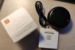
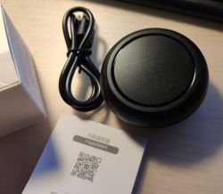
    Universal infrared remote control set with a USB-C cable and manual. Universal IR Remote IRC03 with USB-C Cable and Manual Back of a universal infrared remote control with technical specifications visible.

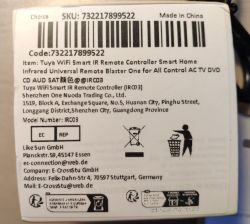
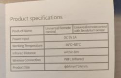
    This is the information on the packaging and in the instructions (There also seems to be a version with an integrated thermometer and humidity meter.):
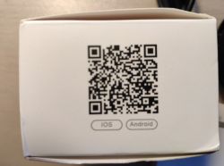
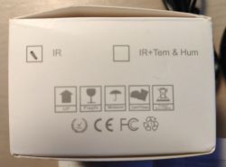
    Photo of packaging with a QR code and iOS and Android labels. IR remote packaging with informational symbols. Information on the packaging of the Tuya WiFi Smart IR Remote Controller IRC03. Product specifications on the packaging of a universal infrared remote control.

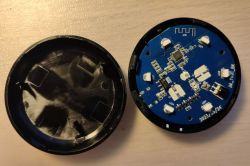
    The housing is easy to open, but care must be taken as the latches (four) can easily break off.
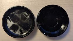
    Two black circular case components with holes and notches. Photo of an open IRC03 Universal infrared remote control, showing the circuit board and interior casing.

    The device differs from the other documented types. It has only one circuit board and the SoC is soldered on directly without a breakout board:
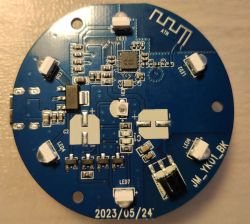
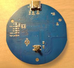
    Circuit board with electronic components and LEDs. IRC03 Universal device circuit board with visible pin labels.

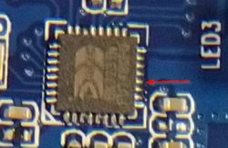
    As you can read on the ic, it is a BK7231N. Flashing Open Beken works without any problems. Contact is made via well-labelled test pins on the back of the board.
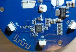
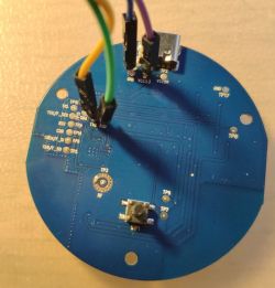
    Close-up of the circuit board of the IRC03 Universal remote with visible BK7231N chip. Interior of IRC03 universal remote with visible PCB and connected wires.

    The Pin layout is as follows:
    PinSetting
    7IRSend
    8IRRecv
    9Btn
    24WifiLED

    Configuration:
    Code: JSON
    Log in, to see the code


    Apart from the slightly different board, it is easy to get the device up and running with Open Beken and connect it to HA. Thanks to the easily accessible TP, everything is without any problems. The pins were quite easy to guess. Everything works as with the existing IR devices.

    Cool? Ranking DIY
    About Author
    atomphil
    Level 10  
    Offline 
    atomphil wrote 30 posts with rating 16, helped 4 times. Been with us since 2023 year.
  • ADVERTISEMENT
  • #2 20803287
    p.kaczmarek2
    Moderator Smart Home
    Thanks for the teardown. It's interesting to see that the manufacturer didn't solder any of the big electrolytic capacitors on that PCB.
    Helpful post? Buy me a coffee.
  • #3 20816402
    atomphil
    Level 10  
    Is there a way to send raw codes? I have a number of RGB LED bulbs and fairy lights that I would like to switch with the controller. I have not found any protocols for them.
  • #4 20948893
    iff7378
    Level 4  
    I just got 3 of these from Aliexpress and am struggling to flash it. I cannot get the Easy UART Flasher to get the bus. Running on Ubuntu, the flasher works great with Mono.

    I have been powering it from the USB C port and just connecting TX and RX to my programmer. I was expecting just to power cycle it by unplugging and reconnecting the USB power.

    Then I tried soldering to GND and 3.3v. Somehow simply soldering the wires to the test ports made the voltage regulator get super hot. I am certain i didn't short the 3.3V and GND pads together, but I mustve done something bad.

    Tried the second one, no luck through USB power. Soldered wires to its 3.3v and GND pads then connected it to the programmer. When trying to power cycle, as soon as I connect the 3.3v line to the programmer, it dies for an instant and the Flasher loses the serial connection. I've used this programmer to flash Tasmota a different IR device with an ESP chip and it worked great.

    These boards don't have a pad for CEN so I don't think I can do that method. Any ideas would be great. I can't figure out why powering it from USB doesn't work.

    Added after 1 [hours] 24 [minutes]:

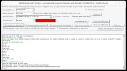
    Screenshot of BK7231 Easy UART Flasher program showing Reading failed error.

    Success kinda...I got the bus connected. The RST test point is the CEL pin so I used that to reset the chip.

    But now its unable to read the firmware on the chip? Tried all 3 baud rates with no success. The slower baudrate, 115k didnt work with the same failed to read. The faster one wasn't able to set the baud rate.
  • ADVERTISEMENT
  • #5 20950309
    p.kaczmarek2
    Moderator Smart Home
    Hello @iff7378 . I haven't tried the flasher on Mono. Please try hid_download_py approach:


    Added after 21 [seconds]:

    https://github.com/OpenBekenIOT/hid_download_py
    Helpful post? Buy me a coffee.
  • #6 20950671
    iff7378
    Level 4  
    Edit - I got this working, read to the end!

    I tried the python program and was able to read the firmware but got a CRC check failed at the end.

    I then tried to write the firmware using:
    (env) ian@ian-XPS-15-9560:~/hid_download_py$ sudo /home/ian/hid_download_py/env/bin/python3 uartprogram OpenBK7231N_QIO_1.17.453.bin -d /dev/ttyUSB0 -w
    UartDownloader....
    programm....
    CRC not equal : |##################################################|[ 13.6k/s]


    Also got the same CRC issue. I thought this was mainly due to a BK7231N vs BK7231T issue. This IR device is certainly BK7231N as shown earlier and you can see in my command above I used the BK7231N firmware.

    Any other ideas? Much appreciate the help. At least now I was able to read and write to the chip.

    Nevermind!! I need to read the documentation :) After setting the flags correctly:

    (env) ian@ian-XPS-15-9560:~/hid_download_py$ sudo /home/ian/hid_download_py/env/bin/python3 uartprogram OpenBK7231N_QIO_1.17.453.bin -d /dev/ttyUSB0 -s 0x0 -u -w
    UartDownloader....
    programm....
    Write Successful: |##################################################|[ 13.8k/s]

    Thanks for the help!
  • #7 20950838
    p.kaczmarek2
    Moderator Smart Home
    I am glad to hear that the problem is resolved, let me know if anything else is needed
    Helpful post? Buy me a coffee.
  • ADVERTISEMENT
  • #8 20974443
    jkwim
    Level 12  
    I have the same product with the same PCB version.

    Just that the screen printing is messed up (text reversed)

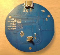
    Yours:
    Round printed circuit board (PCB) with various pin labels and components.

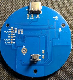
    Mine:
    Blue round circuit board with USB-C port on top and a button at the bottom.

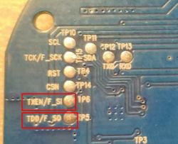
    Having seen the letters SI & SO clearly, I began to investigate more as these could be the MOSI and MISO pins.

    Photo of the back side of a PCB with reversed silkscreen text.

    Recently there was an updated discussion about using MOSI pin for driving WS2812B LED strip.

    So I was interested in finding out whether this IR device also can work as a WS2812B LED Driver.

    Read more here.

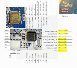
    This is my attempt to map the connections from the chip side:
    Diagram and photos of PCB with highlighted pins of the BK7231T chip.

    However so far I have not been able to establish the connectivity to the Test Pad using continuity testing.

    This is something that I want to pursue as then I can make this device also dual purpose.
  • #9 20974503
    p.kaczmarek2
    Moderator Smart Home
    @jkwim please set P16 to AlwaysHigh, check with multimeter is pad 3.3V. Then set to always low, check again for 0.0V on the pad.

    It's possible that those pads are not P16.

    Please consult SPI flashing tutorial: https://www.elektroda.com/rtvforum/topic3931424.html
    SPI flashing is also using SPI protocol, but in this case, for flashing, the pins used are P20, P21, P22, P23 (SCK, CSN, SI and SO).
    So, it's very possible, that you have the "flashing SPI port" there, not the "output SPI", sadly.
    Helpful post? Buy me a coffee.
  • #10 21183559
    Cramp1017
    Level 4  
    Hi, I lost my original Tuya firmware backup for this device. Can anyone share their own backup so I can go back to factory? (I want to give the device away)
  • #11 21201546
    jkwim
    Level 12  
    p.kaczmarek2 wrote:
    @jkwim please set P16 to AlwaysHigh, check with multimeter is pad 3.3V. Then set to always low, check again for 0.0V on the pad.

    It's possible that those pads are not P16.

    Please consult SPI flashing tutorial: https://www.elektroda.com/rtvforum/topic3931424.html
    SPI flashing is also using SPI protocol, but in this case, for flashing, the pins used are P20, P21, P22, P23 (SCK, CSN, SI and SO).
    So, it's very possible, that you have the "flashing SPI port" there, not the "output SPI", sadly.


    I revisited the P16 issue hoping to connect some WS2812 LEDs to the unit.

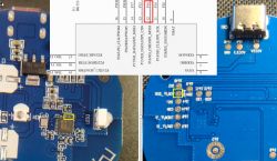
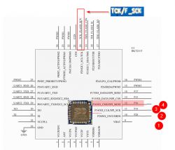
    I was hoping to find a connectivity to Pin 12 of the Chip which is designated as P16

    PCB with a microcontroller and pin connection diagram, highlighting pin 12 labeled as TCK/F_SCK.

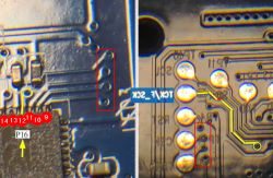
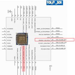
    I found that PIN 12 is connected to the pad labelled TCK/F_SCK.

    Close-up image of circuit boards showing PIN 12 and TCK/F_SCK connections.

    I verified the continuity between PIN 12 and this pad.

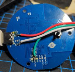
    Then I connected a WS2812 LED Ring as shown in the following picture:

    Close-up of the back side of a round printed circuit board with connected wires.

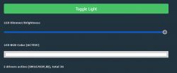
    Screenshot of a selection menu with two options for P16 and P17 in the interface.

    The LEDs do not get lit up after loading the driver using command:
    startDriver SM16703P


    User interface for controlling LED lights.

    Wonder what am I doing wrong here.
  • #12 21201631
    p.kaczmarek2
    Moderator Smart Home
    See related topic:
    https://www.elektroda.com/rtvforum/topic4057187.html
    You need to at least have SM16703P_Init called as well:
    
    startDriver SM16703P
    SM16703P_Init 16 
    startDriver PixelAnim
    
    Helpful post? Buy me a coffee.
  • ADVERTISEMENT
  • #13 21202017
    jkwim
    Level 12  
    jkwim wrote:
    I was hoping to find a connectivity to Pin 12 of the Chip which is designated as P16


    I found that PIN 12 is connected to the pad labelled TCK/F_SCK.


    Can you confirm whether my interpretation of pin layout is correct here?

    When I look at the chip orientation, PIN 12 is on to the right hand side, 4th pin from bottom.

    The screen print on the device (Which is anyway printed in reverse) designates the pad with TCK/F_SCK which happens to be the 4th pin on the top edge of the chip if counted from left.


    Chip pin layout diagram with labels and highlighted pins.
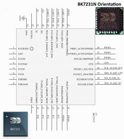
  • #15 21202312
    jkwim
    Level 12  
    divadiow wrote:
    because annoyingly that image is unintuitively oriented with pin 1 on the bottom left. I made the below for this thread/device https://www.elektroda.com/rtvforum/topic4066219.html

    Diagram of BK7231N chip orientation and pinout with a photo of the chip.


    Yes, I also figured it out the hard way now. So the PCB screen print is correct.

    PCB diagram showing pin labels and connection paths.

    Now I need to figure out how to solder a tiny wire strand on to PIN 12 as there are no connections from the chip for these pins.

    Image of an integrated circuit on a PCB with a pin marked by a red arrow.

    I have a fine tip soldering bit but never have attempted a job at this level before. Probably only a single wire strand will fit in there.

    Perhaps its not worth the effort.
  • #16 21203255
    divadiow
    Level 34  
    Yes, that will be tricky. Shame the device doesn't use a CBU module with a nice easy P16 routed to a contact.
  • #17 21204580
    p.kaczmarek2
    Moderator Smart Home
    Routing out P16 is indeed a bit harder than soldering to a premade pad, but it's certainly possible. It has been already shown in one of the tutorials:
    How to access hardware SPI port on CB2S? P16 (MOSI) GPIO breakout method
    Helpful post? Buy me a coffee.

Topic summary

The discussion revolves around user experiences with the Tuya WiFi Smart IR Remote Controller IRC03, highlighting its compact design, effective illumination with seven IR LEDs, and included USB-C cable. Users share insights on flashing the device, troubleshooting issues with firmware, and connecting RGB LED strips. Several participants discuss technical challenges related to pin connections, firmware compatibility, and the potential for using the device as a WS2812B LED driver. There are also inquiries about sending raw codes for controlling various devices and requests for original firmware backups.
Summary generated by the language model.
ADVERTISEMENT