logo elektroda
logo elektroda
X
logo elektroda

[Solved] How do you upload Tasmota to a no-name wall plug with no markings on the PCB?

ra_dzik 1272 8
ADVERTISEMENT
Treść została przetłumaczona polish » english Zobacz oryginalną wersję tematu
  • #1 20937003
    ra_dzik
    Level 7  

    Colleagues,

    I have a request for people who are involved in the Tasmota and home automation thread. There is a lot of material on the web, but I wanted a switch that is touch-sensitive, without a neutral wire, has WiFi communication and can be controlled via RF 433 MHz.

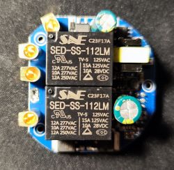
    I found such on "one of the popular auction sites", everything works as it should, but I would like to zap Tasmota there, but the board is not completely described. It's not a Sonoff or a more popular model, just a typical no-name.

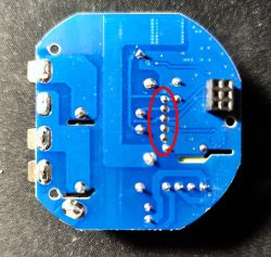
    Anybody had to deal with such a PCB? I suspect that the RX, TX, VCC and GND pins are the ones marked on the photo, but there is no marking on them.

    Anybody knows how to plug in to load Tasmota into this invention?

    I would be grateful for help. Circuit board with SED-SS-112LM relays and soldering points. Printed circuit board of an unidentified switch with highlighted solder points. .
  • ADVERTISEMENT
  • #2 20937294
    krzbor
    Level 27  
    Unless you give a picture of the chip responsible for WiFi it will be difficult to answer anything. Tasmota is for ESP processors. There are also solutions for other processors to ensure compatibility with Tasmota Link .
  • ADVERTISEMENT
  • #3 20937462
    ra_dzik
    Level 7  
    On this first board, there is only a tiny IC marked 8A6D and an MT2513 IC (ASX 041N).
  • ADVERTISEMENT
  • #4 20937826
    krzbor
    Level 27  
    This MT2513 is more of an inverter to power the whole thing.

    Added after 1 [hours] 56 [minutes]:

    See if the circuit for communication is not on the other board. Next to these circuits there is a distinctive snake on the board - this is the WiFi antenna.
  • #5 20938143
    ra_dzik
    Level 7  

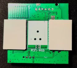
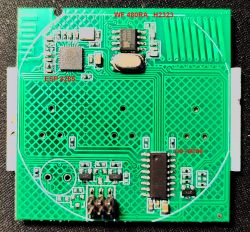
    There is a second touch tile, here it is:
    - ESP 8285
    - WF 480RA (H2323)

    the board marked as WIFI W6B

    so I guess it connects to this touch board, but it too has no marking, which pio is RX, TX, VCC and GND :-( Electronic board labeled WIFI W6B with visible traces and connectors. Green PCB with markings ESP 8285 and WF 480RA H2323, missing pin descriptions RX, TX, VCC, and GND. .
  • Helpful post
    #6 20938389
    krzbor
    Level 27  
    The good news is that the ESP8285 is the same as the ESP8286 with an extra 1MB of Flash. It runs Tasmota on it. The bad news is that it may not be straightforward to program this chip. It looks very similar to this Link .
  • ADVERTISEMENT
  • Helpful post
    #7 20938860
    p.kaczmarek2
    Moderator Smart Home
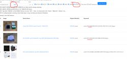
    Colleague @krzbor gave the solution, the linked topic describes the programming. I'll also add, that the board with WiFi has the designation W6B, so just enter it on our site:
    https://openbekeniot.github.io/webapp/devicesList.html
    And immediately there is the result:
    Device list with W6B designation displayed on a website. .
    Helpful post? Buy me a coffee.
  • #8 20938864
    ra_dzik
    Level 7  

    Super! You are a champion! Thanks for your help. I'm working!
  • #9 20938865
    ra_dzik
    Level 7  

    Fellow forum members helped. A similar topic was dissected and I got a helpful link. Thanks!

Topic summary

The discussion revolves around uploading Tasmota firmware to a no-name wall plug with an unmarked PCB. The user seeks assistance in identifying the RX, TX, VCC, and GND pins for programming. Initial responses highlight the need for the specific WiFi chip identification, with mentions of an MT2513 IC and a touch tile featuring an ESP8285 chip. The ESP8285 is confirmed to be compatible with Tasmota, although programming may not be straightforward. A helpful link was provided that details the programming process for the board designated W6B, leading to successful assistance from the community.
Summary generated by the language model.
ADVERTISEMENT