logo elektroda
logo elektroda
X
logo elektroda

Flashing ELEGRP single pole light switch CB2S Board with BK7231flasher Guide (SPN10)

thirug010 1101 3
ADVERTISEMENT
  • #1 20937467
    thirug010
    Level 2  
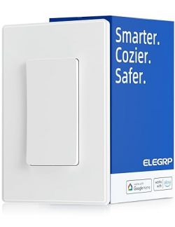
    ELEGRP light switch against packaging with Smarter. Cozier. Safer. text
    ELEGRP Single Pole Light Switch (single or 3 Way)

    This device has CB2S, for a single switch it does not have any Tuya MCU. This regular UART flash the on CB2S and the board is perpendicular to the main PCB, but it is ok to solder the pins for 3v3 GND, TX, RX.

    To open it, use a flat head screw on the bottom of the switch near the metal plate. It will lift the back panel. It has four push mount points. Once you open the first point, everything will fall apart, as shown in the images below.

    Disassembly process of ELEGRP light switch.

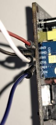
    Solder the 3v3, Gnd, TX, RX on the CB2S board as below connect it to the UART as below, flash the firmware using BK7231flasher or ltchiptool (Start flashing / read dump by connecting ground the CEN pin)
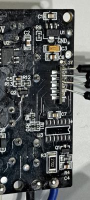
    Close-up of a PCB with soldered wires.

    Close-up of wires connected to a CB2S circuit board.

    UART TX --> PCB RX
    UART RX --> PCB RX
    UART GND --> PCB GND
    UART 3.3V --> PCB 3.3V (preferably use another stable 3.3v power and connect the GND to PCB GND)

    Note: I faced issues with the UART 3v3, so I use another UART on 2A USB power adaptor and connected the GND to common ground as below,
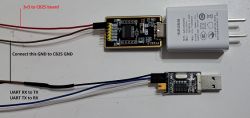
    Connected UART programmer to PCB board with connection labels.

    Note:Make sure to select the option 'Automatically configure OBK configuration on flash write' to ensure to openBK WiFi access point
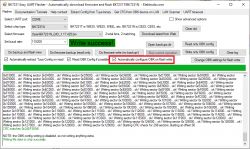
    BK7231 Easy UART Flasher interface with a write success message

    Once the flash is completed, Use the below config for Single switch, Note: No Tuya MCU is present in this switch, it just using gpio pins

    Single Pole 1 Way:
    Code: JSON
    Log in, to see the code


    Single Pole 3Way ( with blue wire version)
    Code: JSON
    Log in, to see the code


    Thanks
    Thirug
  • ADVERTISEMENT
  • #2 20937795
    p.kaczmarek2
    Moderator Smart Home
    Thank you, your entry has been added to our database:
    https://openbekeniot.github.io/webapp/devicesList.html
    By the way, to be clear, if I understand correctly, it's a single device that can be used in a single mode or 3-way (stairs switch) mode, right?

    So you would need ADCSmoother to pair two such devices in a 3way mode?
    https://www.elektroda.com/rtvforum/find.php?q=ADCSmoother
    Helpful post? Buy me a coffee.
  • ADVERTISEMENT
  • #3 20939069
    thirug010
    Level 2  

    Thank you, I will check ADCSmoother option, but this switch comes in 2 versions: 1-way or 3-way.

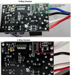
    The 3-way switch has physical components (Not sure, maybe some high current transistor) to convert the AC load output from the Traveler switch to toggle this switch. Please refer to the image below. This input is connected to the P8. The non 3-Way version does not have the input.

    Circuits of 3-way and 1-way switch versions, with marked sections.

    Thanks,
    Thirug
  • #4 21344277
    psyko_chewbacca
    Level 6  
    Hi,

    anyone tried to go through the Cloudcutter way with these?

    My unit has an exploitable firmware, there's even a profile for this particular device in Cloudcutter.
    Yet I'm unable to put the device in slow AP mode...

    I hold either up or down button for 6 seconds, it puts it in fast blinking pair mode.
    In that state, trying to hold yet again either button 6 seconds just seems to reset the unit and put it back into fast blinking pairing mode.

    Thanks
ADVERTISEMENT