logo elektroda
logo elektroda
X
logo elektroda

Flashing Kuled Smart Switch with BK7231N Chip using OpenBK7231T_App on Windows

bgardner46 1170 11
ADVERTISEMENT
  • #1 20325830
    bgardner46
    Level 3  
    I have flashed numerous Kuled smart switches with Tasmota and they work great and are very inexpensive. The latest two I got no longer have the same header holes for flashing or the ESP chip that I am familiar with. After disassembly they have a BK7231N chip soldered directly to the main board and they have a different hole layout presumably for flashing. I will attempt to attach an image.
    I am using Windows, I have a USB to serial 3.3 Volt adapter and have downloaded OpenBK7231T_App and hid_download_py. I also have Python 3.11 installed on my computer. However, after attempting to follow numerous tutorials, I just can't figure out exactly how to install the new code and then flash the chips.
    Any chance I can get a more detailed explanation, I would really like to flash these new chips with your software.
    Thanks.
    Bob
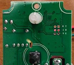
    Flashing Kuled Smart Switch with BK7231N Chip using OpenBK7231T_App on Windows

    Added after 3 [hours] 23 [minutes]:

    It appears that "Touch Switch US (Hidin Tech)" in the tear down list is nearly identical to my switch but, when I click on the link for the tear down, it just takes me back to the full list. Am I doing something wrong?

    Also the pin layout appears to be 2mm spacing and I only have 0.1" headers so I have soldered temporary wires for flashing. Just need to figure out how exactly to do that.

    Thanks
  • ADVERTISEMENT
  • #2 20326543
    p.kaczmarek2
    Moderator Smart Home
    Hello, can you provide more detailed photos? I can't even see the WiFi module (nor the BK chip, if it's directly on board).
    The markings near the place for programming header are also not clear. We might need to follow the PCB traces.

    V and G might be VDD and GND, but R and T? RX and TX? But what about the remaining two ones? And why is R twice? No idea yet.

    The link from teardowns list might be missing if the original author didn't provide the teardown, just gave us the information about the device. Once we have figured out the flashing, I might add a link to that topic there.

    We will be also releasing an English flashing guide video on Youtube soon. That also might help.
    Helpful post? Buy me a coffee.
  • ADVERTISEMENT
  • #3 20327165
    bgardner46
    Level 3  
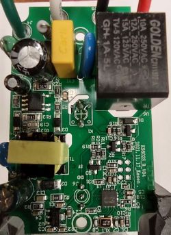
    Okay let me try to provide better pictures although it's really difficult to read the name on the chip without some powerful magnification and getting the light just right. The chip is a BK7231N and here is the chip side of the board.

    Flashing Kuled Smart Switch with BK7231N Chip using OpenBK7231T_App on Windows

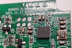
    and here is a close up of the chip

    Flashing Kuled Smart Switch with BK7231N Chip using OpenBK7231T_App on Windows

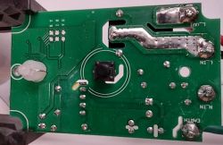
    Finally here is an image of the opposite side of the board

    Flashing Kuled Smart Switch with BK7231N Chip using OpenBK7231T_App on Windows

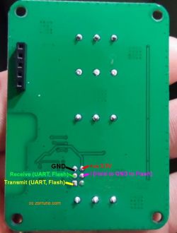
    I found this image from another flashing tutorial and I expect that this is the same layout for the 2 X 6 header

    Flashing Kuled Smart Switch with BK7231N Chip using OpenBK7231T_App on Windows

    Does this help?
    Thanks for any help you can provide.
    Bob

    Added after 2 [hours] 34 [minutes]:

    I have done some additional probing and V and G are 3.3V and ground. R and T go to pins 26 (RXD) and 27 (TXD) respectively. The second R appears to go to pin 21 (CEN) and I goes to pin 19 (SDA/TMS). This is a little confusing but I think is correct.

    Hope this helps.
    Bob

    Added after 2 [hours] 48 [minutes]:

    I've been working on this today and I think I'm really close. I have downloaded the correct binary and soldered wires to the appropriate header locations. The problem I have now is I can't seem to get the uartprogram installed. I have Python 3.11 installed and copied what I believe are the correct files to the python311 folder and run the install.bat file. It looks like it is installing but the screen closes immediately so I can't see the result. When I attempt to type python uartprogram, I get a message back that uartprogram does not exist.
    I have to apologize I do not normally use Python so I'm definitely struggling. Any help or suggestions would be greatly appreciated.
    Thanks,
    Bob
  • #4 20327554
    p.kaczmarek2
    Moderator Smart Home
    Very nice progress.

    Make sure that you are in the same directory as uartprogram. Also put the binary file for flashing there. That way you don't need to worry about the paths.
    Helpful post? Buy me a coffee.
  • #5 20328658
    bgardner46
    Level 3  
    Wow, that was the trick. I just successfully flashed the switch. It worked great. Now I have to figure out which pins control the switch, relay, and LED to complete the configuration. Back shortly.
    Thanks.
  • ADVERTISEMENT
  • #6 20328797
    p.kaczmarek2
    Moderator Smart Home
    That's good, please share configuration when you figure it out, we will add this device to our templates list.
    You can also share how it looks like from the outside (with case) and maybe more details where it was bought.
    Helpful post? Buy me a coffee.
  • ADVERTISEMENT
  • #7 20328904
    bgardner46
    Level 3  
    I will be glad to provide all of the configuration and flashing info once I figure it all out. I have figured out the relay and pushbutton switch, now just need to figure out the LED I/O if there is one. I do have several questions that I have not been able to figure out yet:

    1. Is there a console and can I set a static IP address like Tasmota or do I need to use address reservation on my router?

    2. I have used rules on Tasmota to implement a 3-way switch using MQTT without having to directly connect the two switches. Is there a similar way to do this in your firmware.

    3. Once I have configured a topic in MQTT the full topic in Tasmota is cmnd/name/POWER - I haven't been able to figure out the full topic in the new firmware. Can you help?

    There may be help for all of these questions but I haven't found it yet.

    Thanks again for all your help.
    Bob
  • #8 20330304
    bgardner46
    Level 3  
    Okay, I have figured out the full configuration pins for the switch - relay button, and LED. I also found the console equivalent on the web app - very nice. I have gone ahead and used address reservation on my router to configure a static IP.

    I also figured out the MQTT topic and have been able to successfully control the switch from my Home Automation system which supports MQTT. I see there is a scripting system which may be able to do some of the things I want but have not spent much time figuring out the details.

    I would be glad to submit a tear down and flashing description as I get time. Is there a format or template for producing that.

    Thanks again.

    Bob
  • #9 20330349
    p.kaczmarek2
    Moderator Smart Home
    Good job, don't worry about templates.

    Regarding your questions:
    1. You need to reserve IP for MAC
    2. There is a scripting system and soon it will be more documented and work alongside with Windows Virtual OBK machine/simulator to make development easier, but not yet, what kind of behaviour would you like? Maybe that could be done with Tasmota Device Groups and with a "TglChannelOnToggle" button kind? DGR would keep both devices in sync and TGL would cause a toggle.
    EDIT: I might work even with a simple button, if i understand you correctly.
    BTW: it would work even without MQTT!
    I will look into it and prepare some kind of example for you.
    3. maybe mqtt topics section can help?
    https://github.com/openshwprojects/OpenBK7231T_App


    We can use this topic as a teardown, I'd just need you to add a bit more information here, from a brief glance it looks like the pinout configuration is missing from here yet. Also, maybe you can show how this device looks like from the outside, what was the packaging, where it was bought..
    Helpful post? Buy me a coffee.
  • #10 20330543
    bgardner46
    Level 3  
    It definitely looks like the Device Groups will solve my problem. As soon as I flash a second device, I will give it a try.

    I will also put together a detailed post with all of the flashing and configuration information with pictures as well.

    Bob
  • #11 20330577
    p.kaczmarek2
    Moderator Smart Home
    bgardner46 wrote:
    It definitely looks like the Device Groups will solve my problem. As soon as I flash a second device

    It looks like it for me as well. Don't worry, in OpenBeken device groups are configure through GUI , so you don't even need to know all those strange commands....

    Of course, for more advanced users we have device groups scripting as well.

    PS: Also note that our DGR is compatible with Tasmota DGR... so you can pair our device with Tasmota.
    Helpful post? Buy me a coffee.
  • #12 20355378
    p.kaczmarek2
    Moderator Smart Home
    The final post (flashing description) was moved by me from here to separate topic, please read:
    https://www.elektroda.com/rtvforum/topic3944647.html
    Helpful post? Buy me a coffee.

Topic summary

The discussion revolves around flashing Kuled smart switches equipped with the BK7231N chip using the OpenBK7231T_App on a Windows platform. The user, Bob, encountered difficulties due to the absence of familiar flashing headers and the new chip layout. After sharing images of the board and identifying pin functions, he successfully flashed the switch and began configuring it. The community provided guidance on directory management for flashing, static IP configuration, and MQTT topic setup. Bob also explored device groups for synchronizing multiple switches and expressed intent to document his flashing process and configuration details for future reference.
Summary generated by the language model.
ADVERTISEMENT