FAQ
TL;DR: "even the voltage measurement works" after an ESP‑02S swap; 1 successful transplant reported. Replace the ZTZS Zigbee radio to get Wi‑Fi and keep local control. This FAQ guides DIYers moving from Zigbee to Wi‑Fi or local Zigbee control. [Elektroda, Mad_Maxs, post #20969709]
Why it matters: It helps you choose between staying Zigbee with local control or doing a proven ESP swap—without guesswork.
Quick Facts
- LSPA9 with ZTZS is a Zigbee design; firmware change isn’t expected, so use a Zigbee hub or HA. [Elektroda, p.kaczmarek2, post #20937645]
- It’s cloud‑free locally with Home Assistant + zigbee2mqtt; vendor hubs work but limit control. [Elektroda, p.kaczmarek2, post #20937662]
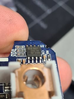
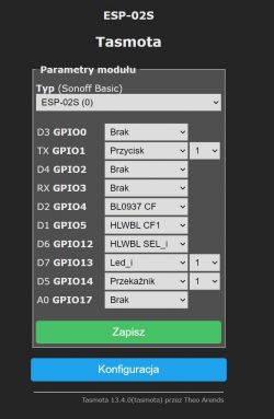
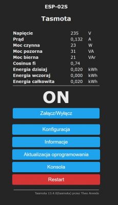
- ESP‑02S swap was confirmed; BL0937 voltage measurement remained functional afterward. [Elektroda, Mad_Maxs, post #20969709]
- After swapping to ESP, flash Tasmota for Wi‑Fi control and configuration. [Elektroda, p.kaczmarek2, post #20937852]
- Calibrate energy readings using VoltageSet, PowerSet, and CurrentSet commands. [Elektroda, p.kaczmarek2, post #20990178]
How do I tell if my LSPA9 uses Zigbee or Wi‑Fi?
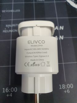
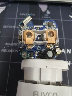
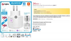
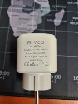
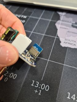
Check the casing for “Wireless Type – Zigbee” and look for a ZTZS radio module. Those markings indicate a Zigbee design, not Wi‑Fi. It then pairs with a Zigbee hub or coordinator. [Elektroda, p.kaczmarek2, post #20937645]
Can I reflash the ZTZS module to Wi‑Fi firmware?
No. “It is not likely that you can change its firmware.” Use a Zigbee hub or replace the radio with an ESP module for Wi‑Fi. [Elektroda, p.kaczmarek2, post #20937645]
How can I run the socket cloud‑free?
It is already cloud‑free when used locally. Set up Home Assistant with zigbee2mqtt and a Zigbee USB dongle. The manufacturer’s hub works, but “you don’t have full control.” [Elektroda, p.kaczmarek2, post #20937662]
I was hunting for a Boot pin—do I need it here?
Not for the stock ZTZS module. Programming that Zigbee radio is not the approach here. Replace the module if you need custom Wi‑Fi firmware. [Elektroda, p.kaczmarek2, post #20937645]
Which Wi‑Fi module is a proven drop‑in replacement?
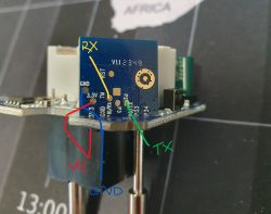
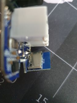
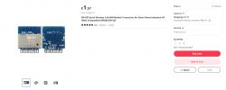
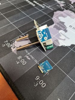
ESP‑02S worked as a solder‑in replacement for ZTZS. The report confirms the socket still read voltage through the BL0937. This is the cleanest path to Wi‑Fi control. [Elektroda, Mad_Maxs, post #20969709]
How do I swap the Zigbee module for ESP‑02S?
Follow this quick procedure:
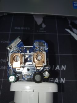
- Desolder the ZTZS Zigbee module from the board.
- Solder an ESP‑02S in its place, matching 3V3, GND, RX, and TX pads.
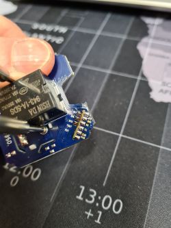
- Power up and verify the BL0937 still reports voltage. [Elektroda, Mad_Maxs, post #20969709]
After an ESP‑02S swap, what firmware should I flash?
Flash Tasmota on the ESP‑02S and proceed with your configuration. That’s the recommended path in this thread. [Elektroda, p.kaczmarek2, post #20937852]
How do I calibrate energy readings after flashing?
Use VoltageSet, PowerSet, and CurrentSet commands to calibrate. “Don’t forget to calibrate...” Run these after flashing to improve accuracy. [Elektroda, p.kaczmarek2, post #20990178]
Will BL0937 measurements still work after the swap?
Yes. The successful transplant retained voltage measurement from the BL0937 chip. [Elektroda, Mad_Maxs, post #20969709]
I got a Zigbee unit by mistake—should I return or mod?
Check the listing and capture screenshots. If it was mislabelled, open a dispute and request a partial refund. Sellers often grant partial refunds. [Elektroda, p.kaczmarek2, post #20937852]
Are there alternatives to ESP for Wi‑Fi conversion?
A BK‑series Wi‑Fi module is another option. An expert in the thread even offered a BK module as an alternative. Consider this if ESP shipping is slow. [Elektroda, p.kaczmarek2, post #20937763]
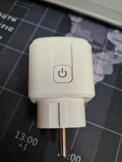
How do I open the LSPA9 enclosure without damage?
The original poster reports the case opens easily in a bench vice. “They are great to open with a vice.” [Elektroda, Mad_Maxs, post #20937583]
Is an ESP swap cost‑effective versus buying a Wi‑Fi socket?
For reference, the ESP‑02S was about £9, and the socket cost £20. Weigh that against your time and soldering effort. [Elektroda, Mad_Maxs, post #20937806]
