logo elektroda
logo elektroda
X
logo elektroda

Identifying TX/RX Pins on EWELINK Zigbee Gateway with ESP32 and EWL-WBT04 Module

yotapaki 1164 21
ADVERTISEMENT
  • #1 21395282
    yotapaki
    Level 2  
    Hello,

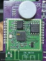
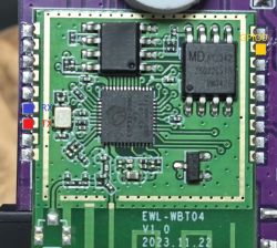
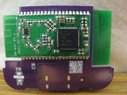
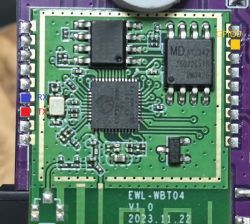
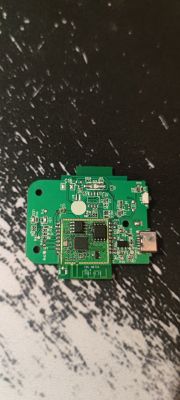
    I am currently working on an EWELINK Zigbee gateway that uses an ESP32 chip. This device includes a module labeled EWL-WBT04, but I’ve been unable to find any documentation or information about it online.

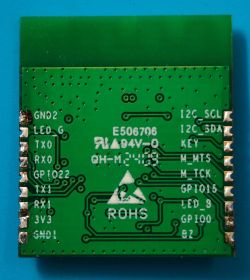
    So far, I’ve successfully identified the GND and VCC pins. The module has a 2x9 pin layout, with two ground pins and two 3.5V VCC pins.

    I’m now trying to locate the TX and RX pins but have encountered difficulties. I attempted to connect my UART controller to each pin individually to find the TX port. However, on some pins, I only receive garbled data (”?????”), and on others, there’s no output during the device boot sequence, suggesting these might not be the correct pins.

    Do you have any tips or methods to help me correctly identify the TX and RX pins?

    Thank you in advance for your assistance!
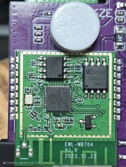
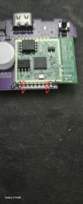
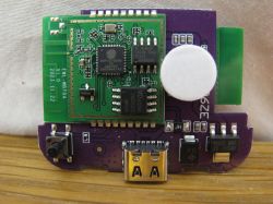
    EWL-WBT04 circuit module on a printed circuit board.
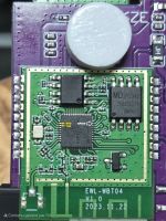
    Electronic module on a circuit board with pin markings.

    AI: Could you provide more details on the method or tools you used to test the pins for TX and RX?
    I connected a cable from the RX port of my UART controller to each pin of the module.
    AI: Are there any additional markings or identifiers on the EWL-WBT04 module that might help in identifying the pins?
    Nope
  • ADVERTISEMENT
  • #2 21396463
    miegapele
    Level 15  
    There is lots of different esp32 chips. If it's zigbee you probably should NOT try to flash it. Likely you will brick it.
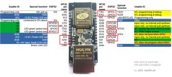
    If REALLY you want to try pinout looks similar to the one on page 13. pins 40 and 41.
  • #4 21396802
    yotapaki
    Level 2  
    Thank you for your response!

    The chip I’m working with is an ESP32 D0WD, which serves as a WiFi module. Additionally, the board includes another module featuring a Zigbee chip (CC2652).

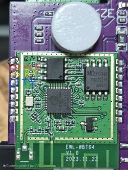
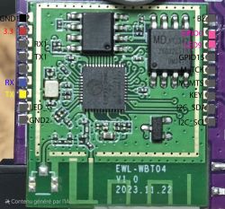
    I’ve managed to locate the TX and RX pins, and I’m trying to enter bootloader mode by grounding GPIO0. Unfortunately, it seems I don’t have direct access to this pin. Do you have any suggestions on how to proceed?

    For reference, here’s some additional information that might help: https://kdrive.bagou450.com/app/share/763082/10c05739-3e48-4751-8a52-ee38994626ed

    Apologies if my questions seem a bit basic—this is my first time working on something this advanced with a board! 😊

    [url=https://obrazki.elektroda.pl/5718286300_1737102141.png]Close-up of a circuit board with marked pins GND, VCC, RX, and TX.[/url>]
  • #6 21398440
    yotapaki
    Level 2  
    I don’t fully understand how to proceed, as the GPIO pins seem to connect to another layer of the PCB.

    However, I noticed that one pin switches from 3V to 0V when I press the button. Could this be GPIO0? I tried holding the button while powering it up, but instead of entering bootloader mode, it just boots normally.
  • #7 21398888
    inot
    Level 37  
    yotapaki wrote:
    I noticed that one pin switches from 3V to 0V when I press the button. Could this be GPIO0?
    .
    This is most likely the CHIP_PU pin that serves as a reset.

    yotapaki wrote:
    I don't fully understand how to proceed
    .
    I thought you knew what I meant by finding the TX and RX pins as I described.
    To check where the GPIO0 signal path goes, use a multimeter and measure whether there is a connection between it and the other pins (one of the eighteen).
  • ADVERTISEMENT
  • #8 21454093
    insmod
    Level 23  
    >>21395282 I received that gateway today, and managed to flash and connect it to Z2M successfully.
    Close-up of an electronic module with clearly marked RX, TX, and GPIO0 pins.
    For pins, treat it like ZBBridge-P that lack some features (i2c rtc, buzzer).
    There is also a PSRAM chip that i haven't managed to get to work.
    ESP32 backup attached.
  • #9 21454302
    insmod
    Level 23  
    And now i've managed to enable PSRAM by doing some pin tracing.
    ESPHome sdkconfig_options are
    CONFIG_D0WD_PSRAM_CLK_IO: "5"
    CONFIG_D0WD_PSRAM_CS_IO: "18"

    I haven't seen any config for ZBBridge-P with psram enabled, but since all pins are the same those would probably work for ZBBridge-P too.
  • #10 21454456
    divadiow
    Level 34  
    didn't know there was a thread for this already. mine arrived today too.
    more pics for library:

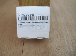
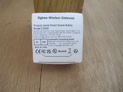
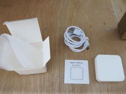
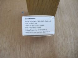
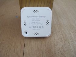
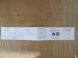
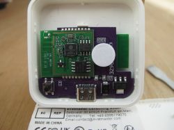
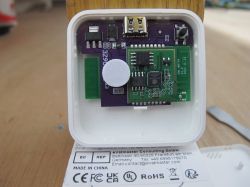
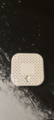
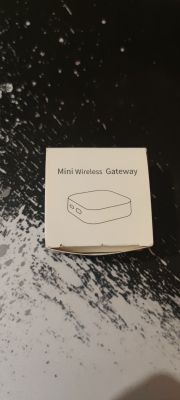
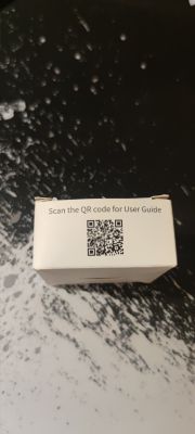
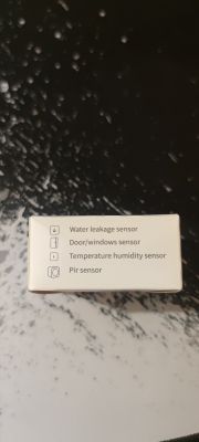
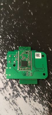
    Packaging of Ewelink Zigbee 3.0 Gateway Hub EZ-MG-ZG-806. Close-up of the Zigbee Wireless Gateway packaging with manufacturer's information. Zigbee gateway starter kit contents on a wooden table. Cardboard packaging with a white label displaying the technical specifications of a wireless device. Zigbee wireless gateway placed on a wooden surface. White square sensor on a wooden surface. Device setup instructions on a wooden table. Zigbee Gateway user manual on a wooden surface. Close-up of an electronic circuit board with visible integrated circuit components. Electronic circuit board with visible USB port and components on a PCB. Interior of an electronic device showing PCBs and a USB port. Close-up of a green printed circuit board with an integrated circuit.

    Added after 37 [minutes]:

    log from that TX labelled. 115200 then 921600

    Code: Text
    Log in, to see the code
  • #12 21487393
    setum
    Level 5  
    >>21454302
    Your mention of ESPHome got me intrigued. Can we install ESPHome in it? How will it work -- similar to Tasmota ZBBridge or similar to ESPHome bluetooth proxy, but with Zigbee (Zigbee Proxy). Do you have the ESPHome yaml for this device?
  • #13 21487805
    insmod
    Level 23  
    >>21487393
    I don't know how Tasmota works - i've never used it.
    But it creates a port for zigbee connection, and i use bluetooth proxy of course.
    Connecting to zigbee is simple - just specify tcp://{ip}:8888
    I tested this with Z2M, and now it works with ZHA.
    I migrated from Tuya WRG1+TYZS3 gateway, flashed with OpenBeken to this.

    I swapped led functions, now red - zigbee connection, blue - wifi status led.
    Remove packages and specify your wifi, api and ota settings.
    substitutions:
      ip: "192.168.0.9"
      powersave: "LIGHT"
    
    esphome:
      name: esp32-zb-bridge
      friendly_name: esp32_zb-bridge
      platformio_options:
        build_flags: "-DBOARD_HAS_PSRAM"
      on_boot:
        priority: 800
        then:
          - switch.turn_on: zigbee_rst
          - delay: 15ms
          - switch.turn_off: zigbee_rst
    
    external_components:
      - source: github://oxan/esphome-stream-server
    
    esp32:
      board: esp32dev
      framework:
        type: esp-idf
        sdkconfig_options:
          CONFIG_ESP32_REV_MIN_3_1: "y"
          CONFIG_D0WD_PSRAM_CS_IO: "18"
          CONFIG_D0WD_PSRAM_CLK_IO: "5"
          CONFIG_BT_BLE_DYNAMIC_ENV_MEMORY: "y"
          CONFIG_BT_ALLOCATION_FROM_SPIRAM_FIRST: "y"
    
    debug:
      update_interval: 5s
    
    # Enable logging
    logger:
      baud_rate: 115200 
    
    uart:
      rx_pin: GPIO23
      tx_pin: GPIO19
      baud_rate: 115200
    
    packages:
      common: !include base/common.yaml
      ota: !include base/ota.yaml
      wifi: !include base/wifi_psk_both.yaml
    
    psram:
      mode: quad
      speed: 80MHz
    
    esp32_ble_tracker:
      scan_parameters:
        interval: 1100ms
        window: 1100ms
        active: false
    
    bluetooth_proxy:
      active: false
      cache_services: false
    
    status_led:
      pin: 
        number: 21
        inverted: false
    
    stream_server:
      port: 8888
    
    binary_sensor:
      - platform: stream_server
        connected:
          name: Connected
          on_press:
            - light.turn_on: red
          on_release:
            - light.turn_off: red
    
      - platform: gpio
        pin: 
          number: 27
          inverted: True
        name: "update_switch"
        internal: True
        device_class: update
        on_click:
          min_length: 1s
          max_length: 3s
          then:
            - switch.turn_on: reboot
        on_double_click:
          min_length: 50ms
          max_length: 350ms
          then:
            - switch.turn_on: fw_update
    
    sensor:
      - platform: stream_server
        connection_count:
          name: Number of connections
      - platform: debug
        free:
          name: "Heap Free"
        psram:
          name: "Free PSRAM"
      - platform: wifi_signal
        name: WiFi Signal Sensor
        update_interval: 3600s
    
    output:
      - platform: gpio
        pin: GPIO2
        inverted: true
        id: status
    
    light:
      - platform: binary
        name: "Red"
        id: red
        output: status
        internal: True
        restore_mode: ALWAYS_OFF
    
    switch:
      - platform: template
        name: FW Update
        id: fw_update
        turn_on_action:
          - switch.turn_on: zigbee_bsl
          - delay: 1s
          - switch.turn_on: zigbee_rst
          - delay: 1s
          - switch.turn_off: zigbee_rst
          - delay: 2s
          - switch.turn_off: zigbee_bsl
          - delay: 25s
          - switch.turn_off: fw_update
    
      - platform: gpio
        id: zigbee_rst
        pin: 15
        name: "Zigbee RST"
        inverted: True
        internal: True
        restore_mode: ALWAYS_OFF
    
      - platform: gpio
        id: zigbee_bsl
        pin: 22
        name: "Zigbee BSL"
        inverted: True
        internal: True
        restore_mode: ALWAYS_OFF
    
  • #14 21525120
    tepliukyurii
    Level 2  
    Wgrałem oprogramowanie https://xzg.xyzroe.cc
    Tak że zmieniłem firmware zigbee na coordinator od tasmota.

    Z Home Assistant pracuję jak z Z2M tak i ZHA.
    Dużo dodatkowych funkcji.
  • ADVERTISEMENT
  • #15 21558029
    sevenissimo
    Level 2  
    >>21487805
    Just wanted to let you know your post and all your work were an immense help! I easily managed to flash ESPHome onto my gateway, so huge thanks for that!

    Unfortunately, Zigbee isn't working yet.
    I'm guessing I need to upload the proper firmware, similar to other CCxxxx-based coordinators.
    I'm just not clear if you did that step, and if so, which firmware version you used.
  • #17 21562627
    sevenissimo
    Level 2  
    >>21558442
    Thanks! I finally uploaded the Zigbee firmware and got ZHA working with this coordinator.
    The hardware seems like good value for money. It should be listed on blakadder.
  • ADVERTISEMENT
  • #18 21582439
    germansunza
    Level 2  
    Hello, I hope you can help me. My English is not good. I have received my gateway and connected it as shown in the image, but I can't get any data. It seems that the TX and RX pins are not correct.
  • #19 21582540
    insmod
    Level 23  
    >>21582439
    They cannot be wrong, i've traced them and flashed successfully via them.
    Perhaps you've accidentally swapped RX and TX? And as far as i remember, they aren't used for logging, so don't expect any output.
  • #20 21583011
    germansunza
    Level 2  
    >>21582540 Connect the module's RX to the UART's TX and TX to RX. I tried to flash it with Tasmota and without success. I tried to do it with Esphome using the script you posted and the same result, GPIO to ground to be able to enter programming mode, voltage at 3.3 volts.

    Identifying TX/RX Pins on EWELINK Zigbee Gateway with ESP32 and EWL-WBT04 Module
  • #21 21583025
    insmod
    Level 23  
    I was using usb to power it, and connecting uart module gnd to any gnd on the whole board (even usb socket body would work). GPIO0 to gnd before powering up.
    Alternatively you could try to read/write firmware via ch341a and a clip.
  • #22 21583302
    germansunza
    Level 2  
    >>21583025 In the end it was my USB adapter, I managed to flash it with Tasmota and it's working fine for the moment.

Topic summary

The discussion revolves around identifying the TX and RX pins on an EWELINK Zigbee gateway utilizing an ESP32 D0WD chip and a CC2652 Zigbee module. The user successfully identified GND and VCC pins but faced challenges locating the TX and RX pins, receiving garbled data during testing. Suggestions included tracing signal paths and using a multimeter to check connections. The user also sought assistance in accessing GPIO0 for bootloader mode, suspecting a button might control it, but encountered difficulties in confirming its function. Responses emphasized careful tracing of signal paths and checking connections to identify the correct pins.
Summary generated by the language model.
ADVERTISEMENT