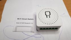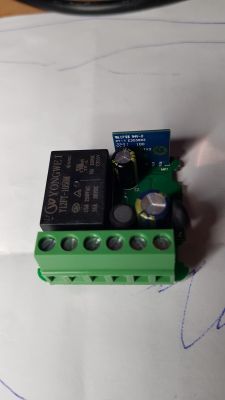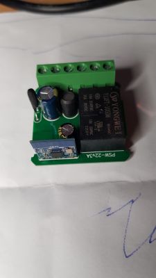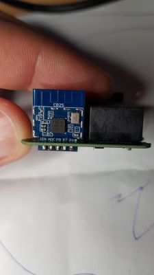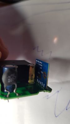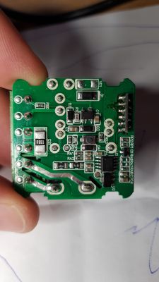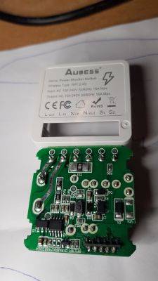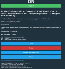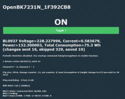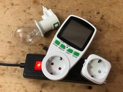
Hello. I would like to present here a short teardown and OpenBeken configuration guide for LSPA9 power measurement socket. LSPA9 comes in various versions, but in this case it's based on CB2S (BK7231N) module and BL0942 energy metering chip with UART interface. I will show here step by step how to flash OpenBeken to LSPA9 and I will also explain step by step how the communication with BL0942 works. The BL0942 protocol section of this article will be dedicated to programmers and people who want to dig deeper into technical details, and can be skipped if you want to just flash OpenBeken and get readouts in Home Assistant.
Related Topics
General topics about my firmware for BK7231:
[BK7231T] My HTTP server, configurator, MQTT support from Home Assistant
WB2S/BK7231 Tutorial - writing custom firmware - UDP/TCP/HTTP/MQTT
Topics about uploading OpenBK to other products:
LED WiFi RGBCW Tuya - teardown, BK7231N, programming with my Tasmota replacement
Garden Tuya CCWFIO232PK Double Relay - BK7231T - Programming
Qiachip Smart Switch - BK7231N / CB2S - interior, programming
My firmware repository:
https://github.com/openshwprojects/OpenBK7231T_App
Purchase of the LSPA9 EU socket
You can find the socket by searching for something like LSPA9 EU Smart Plug WiFi Smart Outlet Socket Voice Control Works for Alexa , I paid about $17 ($14 product + VAT tax and shipping):

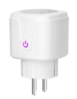
The socket works normally with the Tuya application, but I have already tested it in other topics in this section:
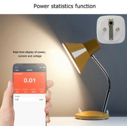
This time there was no shipment from the Czech Republic and the transport took a really long time. More than a month, I guess. Fortunately, no additional payments were required.
The package was sent like from Wiazowna (FASTPRO), but it is obviously just a reshipper.
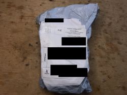
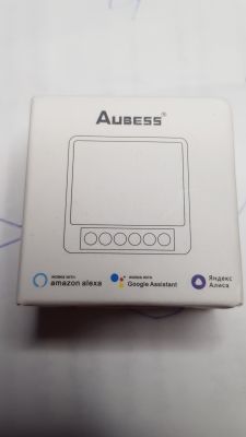
There is only a sticker with the product model (LSPA9) on the package, otherwise it would not be known what socket model it is:
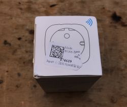
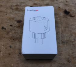
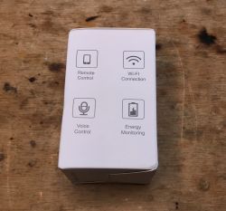
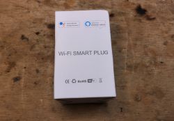
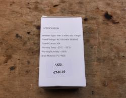
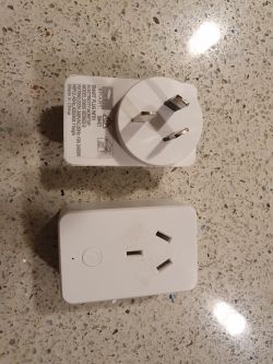
The set includes a socket and instructions:
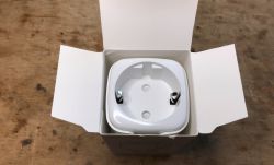


The teardown of the LSPA9 EU
I skipped any tests with the manufacturer's application. This has already been discussed in other topics.
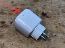
It is hard to get inside, I broke the casing a bit.
Need to pry from the top edge:
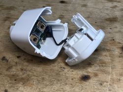
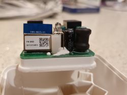
The CB2S module emerges:
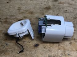
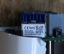
CB2S - a WiFi module based on BK7231N. Already supported by OpenB7231N.
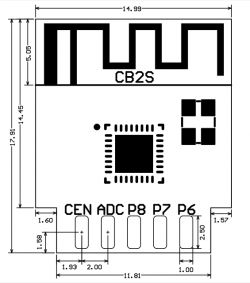
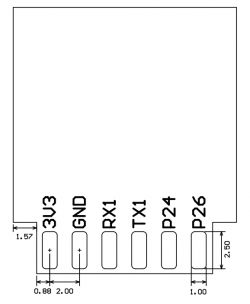
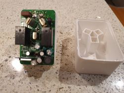
In addition, you can see the energy measurement chip - BL0942, nearby there is a LDO 3.3V AMS1117-3.3 (because the power supply supply provides 12V to control the relay, and the WiFi module requires 3.3V), J3Y transistors (to switch the relay on):
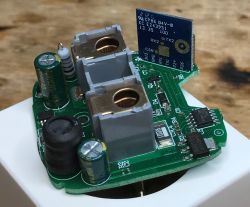
And here is the power supply itself (transformerless!) Is based on the BP2525. This is not the first time I encounter this chip in a smart device.
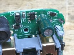
This big resistor is probably a fusible resistor. I can't see any more protection circuitry here. No varistor?
The relay is on the bottom side of the PCB:
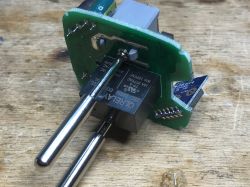
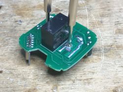
A brief analysis of the PCB with the multilimeter already tells us what is going on here.
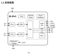
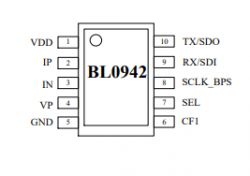
This is a standard smart socket, with BL0942 connected via UART to the CB2S. BL0942 also offers SPI mode, but it is not used here. It's a pity, because the same UART port from CB2S is used for firmware update - will there be a problem with that?
Uploading your own firmware - OpenBK7231N - part 1
Same as in the previous topics in the series:
LED WiFi RGBCW Tuya - teardown, BK7231N, programming with my Tasmota replacement
Garden Tuya CCWFIO232PK Double Relay - BK7231T - Programming
Qiachip Smart Switch - BK7231N / CB2S - interior, programming
Soldering cables to RX / TX and CEN (aka RESET):
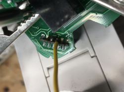
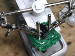
Soldering the cables before the LDO (so that 5V from USB is given at the AMS1117 input):
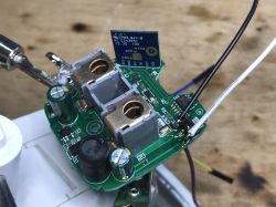
But at this stage I stopped, because first I wanted to see the CB2S communication with BL0942 with my UART converter.
Communication with BL0942
Datasheet of BL0942 shows that baud rate 4200 is used.
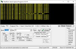
Let's see what UART packets I was able to intercept.
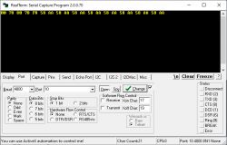
Sent by CB2S:
Sent by BL0942:
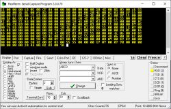
So the host sends two bytes, always the same (even without CRC?), In the form of a request for measurements and BL0942 responds with the measurement results.
I think of the header 0x55 as TuyaMCU, but it's not the TuyaMCU protocol.
One might guess its content here, but we do have a catalog note.
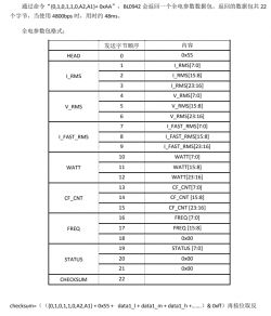
The annotation {0,1,0,1,1,0, A2, A1} proves that the system supports the connection of several sensors (four, that many addresses are allowed by two address bits) to one UART bus. The way this works is that all four devices listen for the call, and only the one whose address is in that call responds to it.
There is a single chip in our socket, however, so no problem.
The measurement results in the packet are broken down into separate bytes. Each of them is a three-byte number. Among others, RMS values, frequency, power.
There is also a one-byte checksum, used to detect possible transmission errors. The checksum is calculated from the remaining bytes of the packet, its value is placed at the end of the packet when it is sent. If, upon receipt, we count the value of the checksum and it is different than the one placed at the end of the packet by the sender, we know that the content of such packet has changed (disturbed) and should be discarded.
In order to verify the formula for the checksum, I wrote a program:
Code: C / C++
Running it on Windows allowed me to quickly verify that the calculations are performed correctly.
I did the rest of the implementation in my OpenBK:
https://github.com/openshwprojects/OpenBK7231T_App/
I have already prepared a UART system with a receiving circular buffer which discussed here (PL only so far) .
Sending a measurement request is simple:
Code: C / C++
It works very much like a simpler version TuyaMCU. I regularly check that the number of bytes in the circular buffer is not less than the length of the expected packet. Additionally, I know that the packet header is always 0x55, so when there is the first other byte, I skip it.
Code: C / C++
Then I know that the whole packet has been received, so I check its checksum.
Code: C / C++
If the checksum is not correct then the packet is discarded - UART_ConsumeBytes (BL0942_PACKET_LEN) .
Now it's time to get the measurements out of it. We need to combine separate bytes into a four byte integer (there are three bytes here, but on this platform the integer is 4 bytes). NOTE: the obtained number will still have to be processed, more on that later.
Code: C / C++
Operator << is a bitwise shift and | is a logical sum.
That will result in an integer like 3569180, which is far from 230V (the voltage we have in Poland at mains).
This integer will have to be divided by a certain constant, which is also used for the calibration.
This constant is calibrated at production time by Tuya, but sadly, when flashing new firmware we have no access to calibration data.
We will have to figure out that constant itself in order to calibrate socket.
How to get that constant?
Well, this is very simple - just measure the voltage with a reliable voltage meter and then take raw_unscaled_voltage sent by plug and divide it by measured voltage.
For me, the constants turned out to be:
Code: C / C++
And finally, this is how you get result voltage, power and current measurements (in V, A and W).
Code: C / C++
How the calibration API is implemented in OpenBK
Of course no one wants to do calibration by hand. That's why I prepared a handy set of functions that will do everything for users. User only inputs the measured value (real voltage, current and power) and the function calculates the calibration constant - BL0942_PREF, BL0942_UREF, BL0942_IREF.
Code: C / C++
The same approach is used for voltage and power.
Flashing the firmware by UART - OpenBK7231N - part2
At first I decided to desolder the BL0942, but do not worry - it turned out to be not necessary. I will just leave the photos here for the reference.
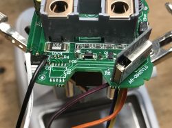
By the way, the Tuya firmware noticed the BL0942 missing right of the bat.
And here is my flashing setup:
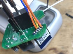
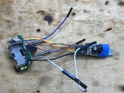
Flashing:
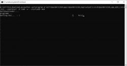
For rebooting the chip, I used the CEN method. It is tricky because you have to connect to CEN to ground for a very short while. That sometimes confuses beginners.
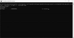
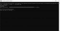
Then I soldered BL0942 and checked flashing again - it still worked. Most likely the baud rate difference and/or the specific packet expected by BL0942 to send reply was enough to ensure that it will stay silent during flashing.
All next software updates were made by OTA (remotely by WiFi), which is already supported by my firwmare for BK7231N and BK7321T.
Of course then you have to setup WiFi SSID, passphrase, etc, but I assume you already know how to do that (if not, see other OpenBeken topics from the series).
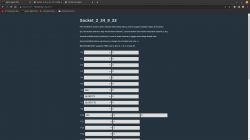
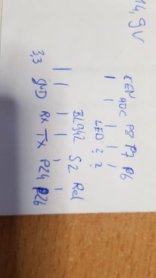
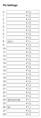
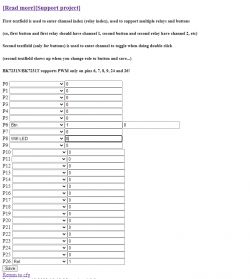
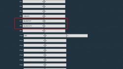
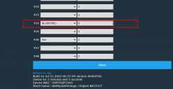
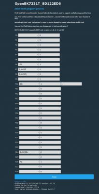
Pin roles:
So how to calibrate BL0942 in OpenBeken?
This section is for all users. You must do that. Otherwise you will get unreliable measurements!
The calibration is very much like in Tasmota, even the command names are the same.
At this point, I assume you already have OpenBeken flashed.
First, run the BL0942 driver. Command:
startDriver BL0942
Remember that you can enter commands at the Javascript frontend app of OpenBeken:
After that, the main page should start showing measurements:
Measurements with no load, before calibration:
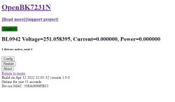
That voltage value is way too high! This is not acceptable. We need to calibrate.
The measurements of 60W bulb without calibration:
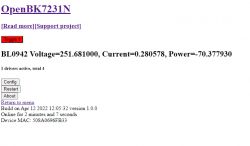
Again, those are wrong.
So, let's calibrate. Take a reliable power meter and measure how much in reality current and power the bulb consumes. Also write down the voltage in the socket. You will need that values later.

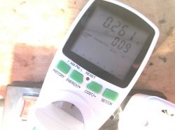
Now, move the plug to the OpenBeken socket and enable it (OpenBeken must be measuring the very same bulb when you do the calibration, the bulb must be on!).
Now, in the command line, type commends: VoltageSet [correntVoltageVal], CurrentSet [correntCurrentVal] i PowerSet [correntPowerVal], and write down the system replies (the correct calibration constants for your very device)
System replies:

So, write down that VREF = 15987.125000
PREF = -683.023987
IREF = 272302.687500
Refresh the page:
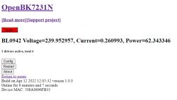
You can also recheck with resistor load:
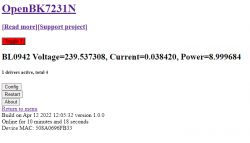
Resistive load is good for doing double-check because you can easily calculate power for that (the cos phi is 1 while for inductive/capacitive load it is not).
2023 UPDATE - THOSE VALUES ARE NOW AUTOMATICALLY SAVED, NO AUTOEXEC.CFG NEEDED. Just use VotlageSet, etc, and it will be remembered by device, saved in flash, kept after reboot.
Anyway, without delving too much into theory, it's time to prepare the config commands set with the calculated calibration constants:
startDriver BL0942
VREF 15987.125000
PREF -683.023987
IREF 272302.687500
Those commands are required to initialize BL0942 driver and set the calibration.
Of course, it would be tedious to type them by hand on each device reboot.
That is why we have a LittleFS file system and "autoexec.bat" system in OpenBK.
So, on your PC, create a file called autoexec.bat and enter those commands.
Then, take that file and drag over the file creation button on OpenBeken Web App Panel:
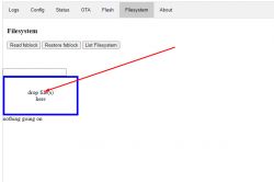
This is how you save the file on LittleFS system of OpenBK.
Then you can also use buttons to list the files, view them, etc.
WARNING: Any OTA update will wipe the commands. This is because they occupy the same region as OTA. Always backup your autoexec.bat on your local machine.
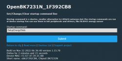
NOTE: The is also a short alternative to LittleFS autoexec.bat. You can use the "short startup command" field configured in options. Remember to enter commands there with "backlog" notation, like that:
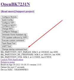
Also note that both autoexec.bat and short startup commands are not executed in "safe mode", i.e. when device fails to fully boot and run for a 30 seconds after booting for several times. The same method can be used to reset device - just power on and power off it three times and never let it run for more than 30 seconds. In safe mode, the device returns to Open Access Point mode and ignores its config (IO pins are disabled, etc).
Configuration YAML foor Home Assistant
Now it's time to send our measurement results to Home Assistant by MQTT.
First, the MQTT needs to be configured in Config->MQTT, just like with any other device.
Then, peek to Config->Generate Home Assistant Config to get short device name, something like obk0696FB33.
You can also copy the configuration from there, but it will work only for relay mode.
Extra manual configuration is required for power metering.
Here is an example:
sensor:
  - platform: mqtt
    name: "BL0942 Voltage"
    state_topic: "obk0696FB33/voltage/get"
    unit_of_measurement: "V"
  - platform: mqtt
    name: "BL0942 Current"
    state_topic: "obk0696FB33/current/get"
    unit_of_measurement: "A"
  - platform: mqtt
    name: "BL0942 Power"
    state_topic: "obk0696FB33/power/get"
    unit_of_measurement: "W"
Replace my device short name with your device names.
After changing configuration.yaml, restart the Home Assistant. Then you should already get measurement results visible on HA charts:
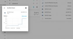
Let's play around a bit. This is power consumption by my notebook in normal power mode:
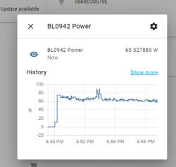
Will "Power saving mode" from Windows change power consumption?
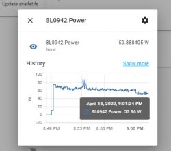
As you can see, not much. What about "High performance" mode?
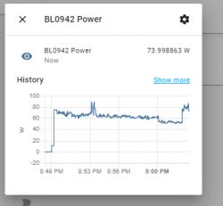
Some more measurements, after a certain time:

Voltage:

I have rechecked it with my Brymen BM857s and indeed, the voltage has changed over time.
Summary
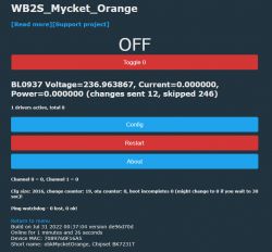
This is how you pair Beken power metering socket with Home Assistant without replacing WB2S/CB2S chip. In future it might be even eaesier, because it might be also possible to flash the LSPA9 remotely with tuya-cloudcutter without even opening the case. The only issue would be that LSPA9 is made in different versions (CB2S + BL0942 or WB2S + BL0937), so it might be hard to determine which version is your socket.
Still, I think the results are worth the effort. My LSPA9 is cloud-free now!
Do not even try to skip the calibration step - the measurements are way off without it.
Also, remember to save your BL0942 init and calibration constant setting commands in LittleFS or startup command - otherwise the BL0942 will forget calibration with next reboot!
Do you like my work?
Please support me at:
https://www.paypal.com/paypalme/openshwprojects
I really need to get more test devices and I plan to support BL0937 and other chips as well soon, so it's crucial to get funds.
Also feel free to register here on Elektroda, I will do my best to help you setup OpenBeken.
PS: I already have BL0937 socket donated to me by other user, so the work is already in progress!
Cool? Ranking DIY Helpful post? Buy me a coffee.



 to their computing prowess
