logo elektroda
logo elektroda
X
logo elektroda

Installing Openbk or ESPHome on TOB9-63M Circuit Breakers: Issues with Cloudcutter and Lightleak

SVA 5196 26
ADVERTISEMENT
  • #1 20723812
    SVA
    Level 2  

    I got a bunch of these TOB9-63M (https://www.aliexpress.com/i/3256805380190385.html?gatewayAdapt=4itemAdapt) circuit breakers with energy monitoring.
    The device is welded shut, so opening it to install openbk using gpio is not a very viable option (don't want duct-taped switches in main breaker panel).
    Wanted to load openbk or esphome variant on this (since all my other devices are on it and connected to HA). Tried cloudcutter (and lightleak) and setup breaker in AP mode. Can't find a profile for this, and by firmware version (1.0.5), tried all the options, but none work. The first step completes OK, but the device stays on and when I restart and start AP mode, it continues to have AP SmartLife-xxxx and not the A* that is expected by cloudcutter.
    Lightleak doesn't even connect to the device (keeps connecting/disconnecting from the SmartLife-xxxx AP).
    Hate to open it (too many devices and would have to break it open making it unusable).
    Any ideas?
  • ADVERTISEMENT
  • #2 20724174
    p.kaczmarek2
    Moderator Smart Home
    I am afraid that you may need to open at least one of TOB9's and take 2MB firmware dump by wires.
    Helpful post? Buy me a coffee.
  • #3 20853888
    jony4t
    Level 8  

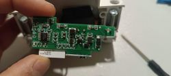
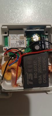
    Hello partners. A few days ago I received the tomz tob9-63. I decided to open the device, it is relatively easy and there are no marks left, you have to extract the golden pins with a flat screwdriver and separate the two faces, inside there is a CBU. Attached photos. I'll try to extract a backup. If you need any more photos, tell me.


    Close-up of a circuit board removed from a device. Interior of an electronic device with visible components and wiring.
  • #5 20854524
    jony4t
    Level 8  

    p.kaczmarek2 wrote:
    Is that BL0942 there?


    Yes. Is it?

    Added after 10 [minutes]:

    It will be enough to install openbeken and configure the pin with BL0942. Or will we have to follow the steps in the link?

    https://www.elektroda.com/rtvforum/topic3995777-30.html#20852685

    Added after 12 [minutes]:

    It will be enough to install openbeken and configure the pin with BL0942. Or will we have to follow the steps in the link?

    https://www.elektroda.com/rtvforum/topic3995777-30.html#20852685
  • #6 20854613
    p.kaczmarek2
    Moderator Smart Home
    The topic you linked is about TuyaMCU device. I am not sure if your device is TuyaMCU-based yet. It may be worth checking whether that BL0942 is connected directly to BK7231 (in UART or SPI mode, it's also worth checking, we support both), or maybe is it connect via TuyaMCU? Is there a secondary MCU on the board?

    Can you check with multimeter whether RX/TX of BL042 connects directly to RX1/TX1 of WiFi module?

    Still, do 2MB flash backup and try flashing OBK.
    Helpful post? Buy me a coffee.
  • #7 20854696
    jony4t
    Level 8  
    I DON'T watch anymore MCU. I am currently attaching the backup copy and the JSON.

    Device configuration, as extracted from Tuya:
    - Button (channel 1) on P17
    - LED (channel 1) on P9
    - Bridge Relay On (channel 1) on P24
    - Bridge Relay Off (channel 1) on P26
    - WiFi LED on P15
    Device seems to be using CBU module, which is using BK7231N.
    And the Tuya section starts, as usual, at 2023424

    JSON

    Code: JSON
    Log in, to see the code
  • ADVERTISEMENT
  • #8 20854728
    p.kaczmarek2
    Moderator Smart Home
    Good job, so all you need is startDriver BL0942 and calibrate.
    If that is not working, then you need to retry with startDriver BL0942SPI.
    Helpful post? Buy me a coffee.
  • #9 20855531
    jony4t
    Level 8  
    Hello, good evening.
    I have flashed the CBU module using UART successfully.

    To configure the pins:

    P9 = LED 1
    P15 = WIFILED
    P17 = BTN_TGL_ALL
    P24 = BridgeFWD;1
    P26 = BridgeREV;1


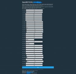
    The BL0942 works perfectly running startDriver BL0942. I haven't had time to calibrate it yet.

    Screenshot of the OpenBK7231N configuration interface with pin assignments.
  • #10 20855593
    p.kaczmarek2
    Moderator Smart Home
    Please include JSON template from the web App if you can
    Helpful post? Buy me a coffee.
  • #11 20855733
    jony4t
    Level 8  
    Would that be correct? Thanks for your help.


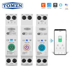
    View of three TOMZN WiFi circuit breakers on a DIN rail with a mobile app

    Code: JSON
    Log in, to see the code
  • #12 20856127
    p.kaczmarek2
    Moderator Smart Home
    Helpful post? Buy me a coffee.
  • #13 20857158
    jony4t
    Level 8  

    Hello, good evening.

    Today, I calibrated tomz.

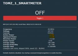
    I have noticed that the real power is changed with the reactive power, therefore the power factor is wrong.
    Furthermore, when consumption is removed, the counter never reaches zero.

    How can I change the data from reactive power to power?

    And how can I make the consumption zero?

    TOMZ_1 smart meter interface displaying energy data, including active, apparent, and reactive power.
  • ADVERTISEMENT
  • #14 20858182
    jony4t
    Level 8  

    At the moment, I have seen that flags 38 contemplate the option of setting the power to zero when the relays are open.
    I have not been able to correct or change the MQTT topic from real power to reactive power.
  • ADVERTISEMENT
  • #15 20858198
    p.kaczmarek2
    Moderator Smart Home
    Okay, so the command to clear stats is: EnergyCntReset
    as per our docs: https://github.com/openshwprojects/OpenBK7231T_App/blob/main/docs/commands.md
    So you think that values of real power and reactive power are swapped?
    Which driver are you using, BL0942 or BL0942SPI?

    I am not the author of BL0942SPI, there might be a bug in the code that I need to fix...
    Helpful post? Buy me a coffee.
  • #16 20858227
    jony4t
    Level 8  

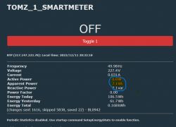
    I am using BL0942. In other plugs, they work fine. But in this new device, I don't know why it appears rotated. I connect a 400W power resistor. 400VAR appears on the screen. Since it is a pure resistance, it should not be reactive energy.
    Screenshot of the TOMZ_1_SMARTMETER interface showing energy measurements with values of 0W active power and 7.1 VA apparent power.
  • #17 20858254
    p.kaczmarek2
    Moderator Smart Home
    And you have other BL0942 devices and they work fine? This is very strange.


    Well, maybe I could create a flag for you, something like "swap" option, but it seems very odd.

    Are all your devices on the same OBK version? Maybe something was broken in the update?
    Helpful post? Buy me a coffee.
  • #18 20859055
    jony4t
    Level 8  
    Since I have a second unit of the same model, I'll flash it to see if the same thing happens. I'll comment on it this afternoon.


    Added after 10 [hours] 17 [minutes]:

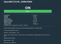
    hello, good afternoon. I have tried with the other device I have with BL0942. Same brand and model. Ocurrs the same. The power appears in reactive power, and not in active power as it should be. OpenBK7231N control panel screen displaying frequency, voltage, current, and power information.
  • #19 20868929
    jony4t
    Level 8  

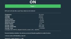
    I have new news about the active power measurement error in the TOMZ 63. When flag 25 is activated, it begins to measure but as if it were pouring energy, negative data appears. Likewise, the reactive energy is very high. Energy monitoring system interface with negative active power
  • Helpful post
    #20 20869347
    johanvdm
    Level 1  

    I have the TOMZN TOB9-VAP. After having it flashed with OBK, I have been struggling with the device getting very hot, also experiencing it to report a couple of Watts even if it has no load powered. Turns out that my config for pins #24 and #26 was incorrect. It should not be configured for Rel and Rel_N respectively. The following pin config worked for me:
    "24": "BridgeFWD;1",
    "26": "BridgeREV;1"
    Also check your channel grouping. Mine was "1".

    This solved both the heating problem as well as the no-load current reporting problem.
    For the latter, I had Flag #25 & #38 also set.

    Anyway, the above worked for me. Worth checking your PIN config out.
    I also think the device template might need to be double-checked, as it also shows the Pin #24 and #26 as relay: https://github.com/OpenBekenIOT/webapp/commit/5e6cd9f5f9e4254d279ed27943c299b585337817

    For a similar setup, see also: https://www.elektroda.com/rtvforum/topic3934580.html

    Hope this helps.
  • #21 20869388
    p.kaczmarek2
    Moderator Smart Home
    Thank you for reporting the problem, @johanvdm . I don't have those devices personally so it's hard for me to check what config will work the best, but you're not the first one to point this issue, so I decided to change all pins of similiar devices to bridge roles:
    https://github.com/OpenBekenIOT/webapp/commit/6e0ac72c19065d843c4af22c0324918dcaf8dcb3
    I hope this will help. If something is still incorrect, let me know.
    Helpful post? Buy me a coffee.
  • #22 20869672
    jony4t
    Level 8  

    Good morning. It is true that the device got hot. I have changed the remote configuration, I will check that the temperature has dropped.
    I was totally unaware of this type of bridge relay.
    It is exactly the same device that you show in the link. https://www.elektroda.com/rtvforum/topic3934580.html
    Seeing that it worked, I thought it was the correct function.
  • #23 20869685
    p.kaczmarek2
    Moderator Smart Home
    I am glad to hear that the problem is resolved, let me know i anything else is needed or if you find any other incorrect template on our devices database
    Helpful post? Buy me a coffee.
  • #24 21157691
    polarbeer
    Level 1  
    I have set this up and allocated the pins as follows:

    
    {
      "vendor": "Tuya",
      "bDetailed": "0",
      "name": "Full Device Name Here",
      "model": "enter short model name here",
      "chip": "BK7231N",
      "board": "TODO",
      "flags": "0",
      "keywords": [
        "TODO",
        "TODO",
        "TODO"
      ],
      "pins": {
        "9": "LED;1",
        "15": "WifiLED_n;0",
        "17": "Btn;1",
        "24": "BridgeFWD;1",
        "26": "BridgeREV;1"
      },
      "command": "backlog startDriver BL0942;",
      "image": "https://obrazki.elektroda.pl/YOUR_IMAGE.jpg",
      "wiki": "https://www.elektroda.com/rtvforum/topic_YOUR_TOPIC.html"
    }


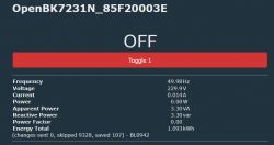
    However, the power is still incorrect for a purely resistive load:
    Screenshot of OpenBK7231N interface with electrical parameter readings.
  • #25 21157709
    p.kaczmarek2
    Moderator Smart Home
    I will add this template to database, what is your device model? Is it 100% the same as in the first post - TOB9-63M?
    Helpful post? Buy me a coffee.
  • #26 21306290
    agarg
    Level 2  
    >>20853888
    I wonder if the relay in the 2nd picture can handle 63 amps. From size, I would have guessed 16 amps!
  • #27 21335022
    felipecrs
    Level 1  
    >>20869347 @johanvdm, do you remember what firmware version your TOMZN TOB9-VAP was running?

    Mine is running 1.0.15 and I was not able to flash it with cloudcutter.

    Do you happen to have your firmware dump too? If it is the same version, maybe cloudcutter devs can add support for it.

    Thanks in advance.

Topic summary

The discussion addresses challenges in installing OpenBK or ESPHome firmware on TOB9-63M circuit breakers with energy monitoring, which are sealed and difficult to open for GPIO access. Initial attempts using Cloudcutter and Lightleak tools failed due to lack of device profiles and firmware compatibility issues (version 1.0.5). Community members confirmed the device uses a BK7231N chip with a CBU board and a BL0942 energy monitoring IC. Successful flashing requires extracting a 2MB firmware dump by opening the device, which is relatively easy by removing golden pins. A device configuration template was developed, assigning pins for LED, WiFi LED, button, and bridge relay control (P9, P15, P17, P24, P26) and using the "startDriver BL0942" command. Calibration revealed issues with power factor and reactive power readings being swapped with active power, which is unusual compared to other BL0942 devices. Solutions included adjusting flags (e.g., #25 and #38) and correcting pin configurations for bridge relays to prevent device overheating and erroneous no-load power reporting. The device template was added to the OpenBekenIOT webapp device list for broader support. Further firmware version differences (e.g., 1.0.15) may require additional Cloudcutter support. The discussion also highlights the importance of verifying hardware connections (e.g., BL0942 to BK7231 UART/SPI) and the potential need for custom flags to address measurement anomalies.
Summary generated by the language model.
ADVERTISEMENT