logo elektroda
logo elektroda
X
logo elektroda

Modification of CUCO_ZO_V1.1 chip from Gosund strip for MQTT - communication problem

Filip8X8 1131 21
ADVERTISEMENT
Treść została przetłumaczona polish » english Zobacz oryginalną wersję tematu
  • #1 20990368
    Filip8X8
    Level 3  

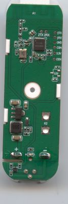
    Hi, I have a wifi chip CUCO_Z0_V1.1 and would like to modify it, install openbeken or something else that works after mqtt.

    It is from a gosund power strip. I have a usb converter for the rx and tx pins. I connect the 3.3v power supply, ground and the rx and tx cables (also tried the other way around) but I can't communicate with it with any program. I know that the IO0 pin is used to reset it but something is not working. Maybe someone could help?
  • ADVERTISEMENT
  • #2 20990403
    p.kaczmarek2
    Moderator Smart Home
    This module is an ESP8266.
    You won't upload OBK there (yet?), but you will upload Tasmota.
    Here's a description of the strip with it:
    Nous Smart Home WiFi Nous A5 strip, ESP8266, Tasmota, CUCO_Z0_V1.1
    Do you know how to upload the batch on the ESP8266? What do you upload with? From what device module?

    Added after 2 [minutes]:

    This is the ESP8266, for there to be bootloader mode IO0 must be on ground at the time of reboot.

    You do it like this:
    1. you connect normally 3.3V, gnd, rx, tx
    2. you connect IO0 to ground
    3. disconnect the whole from the power supply and connect this power supply to boot with IO0 to ground
    4. then esptool.py can load or read the batch, or you can use this:
    https://www.elektroda.pl/rtvforum/topic3990951.html

    If you do it in the other order (for example first connect the power supply and then connect IO0 to ground) it won't start.

    Here you have more info: SmartLife switch - test, interior and programming of light switch on WiFi .
    Helpful post? Buy me a coffee.
  • ADVERTISEMENT
  • #3 20990413
    Filip8X8
    Level 3  

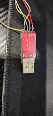
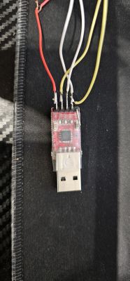
    Ok, give me 5 minutes to test what you write. I will try to upload it using the installer. The programmer I have on it already installed openbk so probably no problem USB to TTL CP2102 adapter with connected wires .
  • #4 20990422
    p.kaczmarek2
    Moderator Smart Home
    Are you programming in or out of the circuit?

    In my opinion, powering directly with 3.3V from a USB to UART converter is not reliable, you may miss the current, but try. Read my topics, I always either plug in 5V before the AMS1117-3.3V (LDO 3.3V) on the board or take 3.3V from my LDO 3.3V with high current capability.

    How does this Gosund strip with this module look like? Potentially there could also be a problem with how the module is in the circuit you may need to solder it out.
    Below is a link to a video from the Elektroda channel where it is shown how to desolder a module like CUCO/TYWE2S/CB2S with braid and flux:
    https://youtu.be/YQdR7r6lXRY?t=107
    Helpful post? Buy me a coffee.
  • #5 20990425
    Filip8X8
    Level 3  

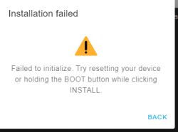
    Something is wrong, I keep getting something like this popping up Installation error message stating Failed to initialize. Try resetting your device or holding the BOOT button while clicking INSTALL.

    Added after 4 [minutes]:

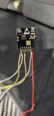
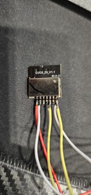
    I have the chip soldered, I have the cables stripped to possibly change something, do you think there could be a problem with the power supply? I can connect a separate 3.3v power supply Close-up of a USB module with attached wires in various colors. Chip labeled XHX 2023 with connected wires, one of which is red. Circuit board with visible wires and CUCO_Z0_V1.1 marking Circuit board with visible wires and CUCO_Z0_V1.1 marking
  • #6 20990445
    p.kaczmarek2
    Moderator Smart Home
    There is no option that it does not work. To try you have:
    1. power it normally, more than once there was a situation on the forum, that it turned out that 3.3V from USB to UART does not work
    2. shorten the wires (the shorter the better, there were also situations that this helped)
    3. swap RX with TX

    Additionally you may want to do as here:
    https://www.elektroda.pl/rtvforum/topic3990951.html
    that is, use esptool.py , at least to make a copy:
    Fragment of a guide on using esptool.py for backing up ESP software.
    if you use esptool.py then we will at least see in the console what goes wrong, whether the COM port is seen, etc

    Added after 53 [seconds]:

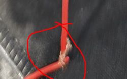
    PS: this also looks bad:
    Damaged red wire with visible break I would check with a multimeter if this is not a broken wire.
    Helpful post? Buy me a coffee.
  • ADVERTISEMENT
  • #7 20990465
    Filip8X8
    Level 3  

    Okay, let's use esptool.py because it tries and tries and doesn't work. Maybe the chip is screwed up, which I doubt. Where would be the best place to start with esptool
  • #8 20990472
    p.kaczmarek2
    Moderator Smart Home
    In this topic
    https://www.elektroda.pl/rtvforum/topic3749207.html
    search for the paragraph "Programming TYWE3S (ESP8266) via UART" and there are instructions there


    I don't think the chip is damaged, unless you treated it with 5V and at the same time with reverse polarity.

    Added after 55 [seconds]:

    EDIT: Just to add, in that topic I wrote about doing a reset with the RST pin, but that is tantamount to unplugging the power quite (that and it will do a reboot)
    Helpful post? Buy me a coffee.
  • #9 20990550
    Filip8X8
    Level 3  

    I see in this topic you are using Arduino to upload your code or something similar, how would I use esptools itself?
  • #10 20990585
    p.kaczmarek2
    Moderator Smart Home
    Indeed, in that topic I downloaded esptool.py together with the package for Arduino. This is because I thought it would be simpler for beginners. Instead, you can install esptool via pip:
    
    pip install esptool
    

    be
    
    pip3 install esptool
    

    Then you can verify its presence via:
    
    esptool.py --version
    

    https://pypi.org/project/esptool/
    Helpful post? Buy me a coffee.
  • ADVERTISEMENT
  • #11 20993234
    Filip8X8
    Level 3  

    I let the topic go for 2 days due to a trip. Back on topic, I have a problem installing the program. (Defaulting to user installation because normal site-packages is not writable)
  • #12 20993272
    p.kaczmarek2
    Moderator Smart Home
    For this reason my suggestion initially was to install together with the Arduino IDE.

    What about the error you gave, I don't associate it, can you specify when it appears and how what you install? Is there a Python already in place?
    Helpful post? Buy me a coffee.
  • #14 20993419
    p.kaczmarek2
    Moderator Smart Home
    This is installed together with the ESP package for Arduino, I gave the path in the linked topic. Without esptool, the Arduino would have no way to upload the batch to the ESP.

    If you don't like either the method with the Python package manager, or with the Arduino, then you can directly from their Github download the zip and extract:
    https://github.com/espressif/esptool
    Documentation:
    https://docs.espressif.com/projects/esptool/en/latest/esp8266/index.html
    By the way, here is also their how to install:
    https://docs.espressif.com/projects/esptool/en/latest/esp8266/installation.html#installation
    Helpful post? Buy me a coffee.
  • #15 21000151
    Filip8X8
    Level 3  

    I will say this. I've given up on the program because I know it's not going to work anyway. It probably won't be able to communicate with it. Unless you have some time, I can make AnyDesk available and if you manage to fix the chip, I can pay you for the work. But yes, I would be in favor of buying a new chip. Where can I buy one?
  • #16 21000164
    p.kaczmarek2
    Moderator Smart Home
    If this Gosunda is not listed here:
    https://openbekeniot.github.io/webapp/devicesList.html
    This I can flash at my place for free, whereby you cover the shipping of all the hardware I could do a teardown both ways (parcel post), but until I physically check it I can't give absolutely 100% certainty that it is flashable, but 99% it is, after all it is ESP.

    I can also flash more devices, as long as they are not devices that are already on this list: https://openbekeniot.github.io/webapp/devicesList.html details on PW

    I'm just building a device base and I don't need to buy a fifth strip for the house myself.

    Flashing remotely is not an option because I like to flash on proven hardware, then it goes smoothly, I do not have time to look for a hardware problem with someone over the internet...

    PS: for the sake of formality, it would also be useful to collect the boot log of this module and possibly remove the screen, because maybe tuya put there something else than ESP?
    Helpful post? Buy me a coffee.
  • #17 21000201
    Filip8X8
    Level 3  

    Hm. Honestly it doesn't make much sense to send a tiny chip for £15 one way through inpost without being sure. Maybe there is another way to do it? It would be nice to revive this strip because I saw that it has a function of measuring current consumption. The power strip itself was working after replacing the capacitors, I replaced them and it works, but it was not possible to connect it. This is why I am changing to a tasmota for example. Unless you explain step by step what to do in arduino ide to get it working.
  • #18 21000295
    p.kaczmarek2
    Moderator Smart Home
    I don't accept the chip itself, I just flash the full devices to make a teardown for the list of themes: https://openbekeniot.github.io/webapp/devicesList.html I need to physically have the whole product at my place to describe and review it. Then I send back flashed and configured as much as possible.

    Esptool you probably have in Arduino IDE in packages.
    For me it is:
    
    C:\Users\Admin\AppData\Local\Arduino15\packages\esp8266\hardware\esp8266\3.0.2\tools
    

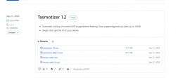
    And if you don't want esptool then there is also Tasmotizer:
    Screenshot of the GitHub release page for Tasmotizer 1.2, showing download options for executable files and source code.
    https://github.com/tasmota/tasmotizer/releases
    Helpful post? Buy me a coffee.
  • #19 21000351
    Filip8X8
    Level 3  

    This program seems better to me. But now I connect the programmer with the chip to the computer while holding the ioo to ground, then after a while I let go and try to install tasmot.bin with the program and it doesn't go. It doesn't communicate. Maybe the chip is indeed the culprit. Can I buy one for this? For this strip?

    Added after 25 [minutes]:

    Good, and maybe you have some smart socket with the same chip that will work on this strip? I can buy a socket from you if you have
  • #20 21000396
    p.kaczmarek2
    Moderator Smart Home
    I don't think the chip is to blame. More likely you are doing something wrong. Maybe the USB to UART converter is not catching something, or you need to set a lower baud, etc. I have already flashing literally hundreds of devices and there were no such problems.

    To be sure, I would possibly:
    - or remove the chip. I would recommend:
    - either take the hot air off the screen from this module and check if it's ESP
    - or just turn on Realterm, select the baud, I don't remember what it was, 115 200 maybe and with IO0 disconnected from ground (i.e. in normal mode, not programming) collect the log from TX1 to see how this chip reports, then we'll know if it's ESP

    I'm afraid ESP-02S will not fit in place of this module, CUCO_Z0_V1.1 even has power and ground in other places, and on top of that I think the problem is with the flashing so ESP-02S you would not program either....

    Added after 37 [seconds]:

    Filip8X8 wrote:


    Filip8X8 wrote:
    Okay, and maybe you have some smart socket with the same chip that will work on this strip? I can buy a socket from you if you have one


    A do you need a socket or do you want to re-solder the module to fit your device?
    Helpful post? Buy me a coffee.
  • #21 21000405
    Filip8X8
    Level 3  

    Solder the chip to the power strip. I may have more use for 3 separate sockets than one. Don't worry about the pin location as long as it works. I can attach the chip loosely somewhere and solder the cables that are needed. Basically, what is needed to communicate with this strip? The rx and tx pins? Or something else? Because I can put another chip+
  • #22 21000418
    p.kaczmarek2
    Moderator Smart Home
    I don't stock the CUCO_Z0_V1.1 modules, you'd have to look to see if you could buy them somewhere, but I think the problem is with your programming anyway. I won't give 100% certainty because you may have somehow rammed the chip, but I don't think so.

    If you want to do a spider then any module will fit, but there is rather no room for that and unless you have rammed the chip then you are taking a circuitous route and more work will go into the spider than if you program this CUCO you have.

    I already forgot, but I see in previous posts that you have this product:
    https://www.elektroda.pl/rtvforum/topic3935059.html#20291828
    In the topic above there is a breakdown of the pins required. Familiarise yourself with the whole topic. There's a bit of it...
    Helpful post? Buy me a coffee.
Topic summary

The discussion revolves around modifying the CUCO_ZO_V1.1 WiFi chip from a Gosund power strip to enable MQTT communication, specifically through the installation of OpenBeken or Tasmota firmware. The user faces challenges in establishing communication with the chip using a USB to UART converter, despite following standard connection protocols. Various troubleshooting steps are suggested, including ensuring proper power supply, checking RX/TX connections, and using esptool.py for flashing firmware. The conversation also touches on the possibility of the chip being damaged and the need for physical access to the device for effective troubleshooting. Users share insights on programming methods, potential wiring issues, and the importance of using the correct baud rate for communication.
Summary generated by the language model.
ADVERTISEMENT