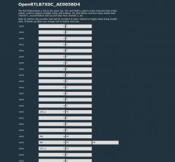
Refoss Smart Plug with Energy Monitoring from Amazon US
RTL8720CF
CSE7759B
I've been trying to get this smart plug with energy monitoring working on OpenBeken. I was successfully able to flash the new firmware after desoldering the chip. The button, relay, and leds all work fine. However, I can't get the CSE7759B working for the life of me.
In the logs it constantly puts out
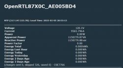
While showing 0 for voltage, current, and power.
When I power the device with 120V, attach a load, and monitor the tx pin of the CSE7759B I was able to capture:
Additional Captures:
Any help with this would be appreciated. I plan to do a proper teardown once I get this working.
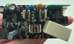
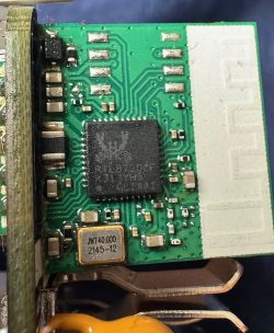
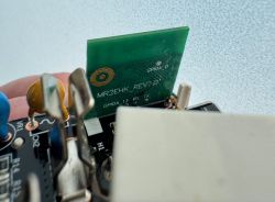
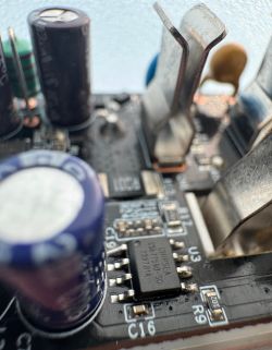
Attatched are pictures of the board
If it helps, this is my current template
RTL8720CF
CSE7759B
I've been trying to get this smart plug with energy monitoring working on OpenBeken. I was successfully able to flash the new firmware after desoldering the chip. The button, relay, and leds all work fine. However, I can't get the CSE7759B working for the life of me.
In the logs it constantly puts out
Info:EnergyMeter:Consumed 252 unwanted non-header byte in CSE7766 buffer
Info:EnergyMeter:Consumed 245 unwanted non-header byte in CSE7766 buffer
Info:EnergyMeter:Consumed 249 unwanted non-header byte in CSE7766 buffer
Info:EnergyMeter:Consumed 249 unwanted non-header byte in CSE7766 buffer
Info:EnergyMeter:Consumed 245 unwanted non-header byte in CSE7766 buffer
While showing 0 for voltage, current, and power.
When I power the device with 120V, attach a load, and monitor the tx pin of the CSE7759B I was able to capture:
35 92 CC 21 F0 ED 61 00 1A 54 55 5A 02 F9 B8 01
62 74 08 D0 94 8F 58 7D 56 35 92 CC 23 8A 52 61
00 1A 55 55 5A 02 F9 B8 00 1C 5D 01 E8 94 8F 58
7D 56 35 92 CC 25 23 B7 61 00 1A 55 55 5A 02 F9
B8 00 0C 5D 02 E8 94 8F 58 7D 56 35 92 CC 26 BD
39 0B 03 A4 AC F9 55 B1 12 96 E1 01 62 E8 08 D0
94 8F 58 7D 56 35 92 CC 28 56 81 61 00 1A 55 FF
55 5A 02 F9 B8 00 0C 5D 02 E8 94 8F 18 5D FC D4
24 98 29 EF D6 61 00 1A 75
Additional Captures:
8D 60 FF 55 5A 02 F9 E1 01 74 6C 17 80 94 2F 58 72 EC 51 48 21 09
EE 7D 8B 02 D4 14 E6 55 5A 09 CB E1 01 5E 6C 17 A0 94 2F 58 72 EC 51 48
61 09 D9 DD 8B 02 D4 14 E6 55 5A 09 CB E1 01 DA 6C 17 A0 94 2F 58 72 EC
51 48 98 09 E8 BC 71 00 8D BD 55 5A 02 F9 B8 00 1E EB 00 3E 65 01 91 B0
51 48 98 09 E1 F1 8B 02 D4 D4 FF 55 E9 12 96 E1 01 5E 6C 17 A0 94 2F 50
72 EC 51 48 21 09 E8 71 71 00 8D BD 55 5A 09 CB E1 05 68 D8 17 A0 94 2F
50 72 EC 51 48 98 09 E8 BC 71 00 8E C0 55 5A 02 F9 B8 00 0A EB 00 3E 65
01 91 B0 51 48 98 09 A1 F1 97 02 E4 14 FE 55 5A 02 F9 B8 01 5A B6 17 A0
94 2F 58 72 EC 51 48 98 09 E8 BC 71 00 8E C0 55 B5 12 96 E1 01 5A 6C 17
80 94 2F 58 72 EC 51 48 98 09 E8 BC 71 00 8E C1 55 5A 04 CB E1 01 68 D8
17 A0 94 2F 18 B9 58 D4 24 98 09 E8 78 71 00 8E D9 FF 55 5A 02 F9 B8 00
0B EB 00 FA 94 2F 18 B9 58 D4 24 98 09 E8 79 71 00 8C D9 FF 55 A9 12 96
E1 01 1A 6C 17 A0 94 2F 10 B9 58 D4 24 98 09 E8 71 71 00 8E F7 55 A9 12
96 E1 01 DA 6C 17 80 94 2F 18 B9 58 D4 24 98 09 D1 F1 8B 02 F4 DC FF 55
5A 02 F9 B8 00 5A B6 17 A0 94 2F 18 B9 58 D4 24 98 09 D1 F1 8B 02 F4 DC
FF 55 5A 02 F9 B8 00 16 EB 00 3E 65 01 94 C3 51 48 61 09 D0 F1 8B 02 F4
DC FF 55 5A 02 F9 B8 01 5A B6 17 A0 94 2F 18 B9 58 D4 24 98 09 FC 02 71
01 7A 16 FD 55 5A 02 F9 B8 00 5A B6 17 A0 94 2F 18 B9 58 D4 28 98 09 F1
09 96 02 F4 5C F5 55 5A 09 CB E1 01 5A 4C 1F A0 94 2F 18 B9 58 D4 24 98
09 FC 04 8B 02 04 2A FD 55 A9 12 96 E1 01 58 4C 1F A0 94 2F 10 B9 58 D4
24 98 09 FC 01 8B 02 04 2A F5 55 E9 12 96 E1 01 50 4C 1F 80 94 2F 18 B9
58 D4 08 98 09 F1 09 82 02 04 2A FD 55 A9 12 96 E1 01 D4 4C 1F A0 94 2F
18 B9 58 D4 24 98 09 FC 09 8B 02 04 2A FD 55 B1 12 96 E1 01 1A 4C 1F A0
94 2F 18 B9 58 D4 24 98 09 FC 00 8B 02 04 2A F8 55 5A 09 CB E1 05 68 98
1F 80 94 2F 18 B9 58 D4 24 98 09 FC 02 71 00 90 85 FF 55 E9 12 96 E1 01
5E 4C 1F A0 94 2F 18 B9 58 D4 20 98 09 FC 09 8B 02 04 2A FD 55 B9 12 96
E1 01 5A 4C 1F 80 94 2F 18 B9 58 D4 24 98 09 FC 02 71 00 91 52 55 69 12
9E E1 01 D0 4C 1F A0 94 2F 18 B9 58 D4
Any help with this would be appreciated. I plan to do a proper teardown once I get this working.
Attatched are pictures of the board


If it helps, this is my current template
{
  "vendor": "Tuya",
  "bDetailed": "0",
  "name": "Full Device Name Here",
  "model": "enter short model name here",
  "chip": "RTL87X0C",
  "board": "TODO",
  "flags": "0",
  "keywords": [
    "TODO",
    "TODO",
    "TODO"
  ],
  "pins": {
    "14": "LED_n;45;0",
    "18": "Rel;44;0",
    "19": "Btn;44;44",
    "20": "LED_n;43"
  },
  "command": "backlog startDriver NTP; startDriver CSE7766",
  "image": "https://obrazki.elektroda.pl/YOUR_IMAGE.jpg",
  "wiki": "https://www.elektroda.com/rtvforum/topic_YOUR_TOPIC.html"
}


