logo elektroda
logo elektroda
X
logo elektroda

OpenBeken IoT device simulator - first early alpha version release for testing

p.kaczmarek2 5973 15
ADVERTISEMENT
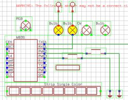
  • Connection diagram in OpenBeken IoT simulator with bulbs and LED strips.
    OpenBeken IoT device simulator allows you to run a virtual OBK device to try out OBK scripting, MQTT setup and Home Assistant pairing. You can also sketch connections of your virtual WiFi module to connect peripherals like buttons, relays, LED strips and even power metering modules and potentiometers.

    OBK simulator features
    - load and save sketches (JSON format) along with a simulated BK7231 flash memory dump (bin format; contains config, LittleFS, etc)
    - draw a circuit almost like you'd draw in Cadsoft Eagle
    - place and use buttons (they are simulated on voltage levels, so all Click, Double Click, Hold Start, Hold Release etc OBK events are working)
    - place relays/bulbs that you can control with buttons or OBK panel or scripts
    - whole OBK HTTP panel works on windows (as a HTTP server on port 80), the Javascript Web App also works, you basically get OBK device on Windows
    - MQTT is also working well, so you can pair your simulated machine with Home Assistant, experiment with HASS automation, test HA discovery
    place single color, CW (CCT), RGB and RGBCW strips and simulate their behaviour
    - use Tasmota Device Groups on Windows (fully functional, simulated OBK device can talk to real Tasmota/Beken devices on your network)
    - use OBK LittleFS to host HTML/javascript files and write OBK scripts
    - send GET packets with SendGET command (fully functional, your Windows OBK sim can send HTTP GET to any server)
    - and more....

    Basic OBK simulator usage
    Start the simulator executable. A basic window with sketch should appear:
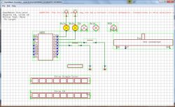
    Screenshot of the OpenBeken IoT simulator with layout of components.
    At the same time, you should get a working OBK page on your local host, the default port is 80, just like with most HTTP programs:
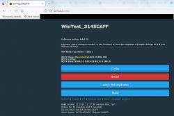
    OpenBeken IoT simulator homepage with device status information and configuration buttons.
    As you can see, it's like a normal OBK device web page. Everything is functional there.
    Now, the basic OBK simulator is simple:
    - in the schematic editor window, you can place relays, buttons and other peripherals, basically to create your virtual OBK device
    - in the OBK simulator page, you can configure your device just like you would be configuring your physical device
    It is important to note that the schematic editor window is interactive, so all buttons there, relays, etc, are really working.


    Loading examples, creating new scenes, saving your work
    OBK schematic editor features a simple menu bar with schematic management options:
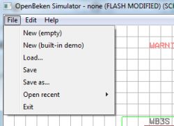
    OpenBeken Simulator window with File menu open.
    Load, save, etc options should be self-explanatory. Your current scene can be easily saved and loaded, just make sure to save manually after making changes to device flash memory - by default, they are NOT saved. To manage virtual devices, use FILE menu:
    - File->New (Empty) - will create an empty scene
    - File->Save - saves changes to current sketch
    - File->Save As - allows you to save current sketch to another file
    - File->Open Recent - provides a list of recently viewed sketches for your convenience:
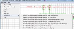
    OpenBeken simulation window with file menu and circuit sketch.
    There are also available OBK simulator sample for download in our repository:
    https://github.com/openshwprojects/obkSimulator

    Changing startup resolution of schematic editor
    Just run your app with the command line parameters:
    
    -w 800 -h 600
    

    You can also create a bat file like:
    
    openBeken_win32.exe -w 800 -h 600
    

    and place it in the same directory as Simulator exe.
    You will also most likely want to skip the self test, so the final bat content will be:
    
    openBeken_win32.exe -runUnitTests 0 -w 800 -h 600
    

    You can change the port of HTTP page, this will allow you to run multiple instances of the simulator on your PC:
    
    openBeken_win32.exe -runUnitTests 0 -w 800 -h 600 -port 81


    Basic operations within schematic editor
    There is almost no GUI at all in the current alpha version of the OBK simulator, so you will need to use hotkeys. They are on the alphanumeric keyboard.
    - Key 1 is Use Tool, which allows you to press buttons, move sliders
    - Key 2 is Move Tool, which allows you to move objects
    - Key 3 is Wire Tool, which allows you to draw wires. Press LMB to draw, and press RMB to change draw mode
    - Key 4 is Delete Tool, which allows you to delete objects, labels and wires
    - Key 5 is Copy Tool, it can be used to quickly make a duplicate of clicked object
    - Key 6 is Info Tool, it prints debug information about object under mouse cursor
    - Key 7 is Text Tool, which allows you to print text on simulator sketch
    Currently active tool is displayed on GUI:
    OpenBeken Simulator interface showing the number of objects and wires, along with the active tool.

    Schematic editor interactions demo
    Let's load a sample scene first - the one with buttons and relays:
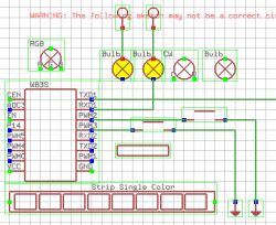
    Circuit diagram using elements such as bulbs, measurement modules, and LED strips.
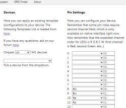
    Now, note down which pins are used for relays and for buttons and configure them in OBK itself. P10 and P11 are relays (bulb icon):
    Table describing UART1 RXD and TXD pins and their serial interface functions.
    PWM2 and PWM3 are buttons:
    Technical documentation excerpt with information on PWM3 and PWM2 connectors.
    This is how I configured them:
    Screenshot of the configuration interface for the OpenBeken IoT simulator.
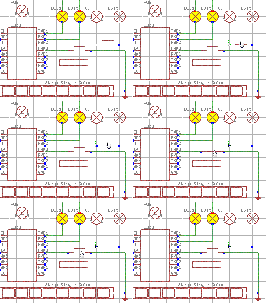
    Now, with left mouse button, click the virtual buttons:
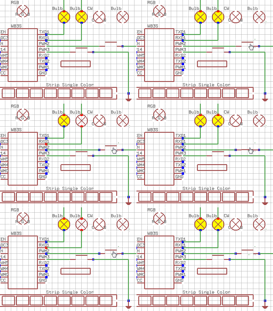
    OpenBeken IoT module schematic with peripheral elements.
    As you can see, the relay (bulb icon) state changes, but with a delay. It's actually expected. It's long known "feature", it's the same in Tasmota. You need to consult our FAQ to read more about it:
    A section of the OpenBeken simulator instructions explaining settings for instant touch switch response.
    So let's enable this flag and try again.
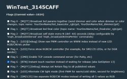
    Screenshot of WinTest OBK user interface with various flag options.
    Now it works even better:
    Schematic diagram with various electronic components and connections on a grid.

    More detailed controls description and examples
    More details about the OBK simulator will be covered in the next topic. Check out our Smart Home Tutorials section for updates:
    https://www.elektroda.com/rtvforum/forum517.html

    Summary
    This is a very early test build of simulator, so there may be many problems and issues which are yet to be solved. Futhermore, the controls will be also improved soon. Still, if you have any feedback, let me know. I will do my best to adjust simulator to suit your needs.

    Cool? Ranking DIY
    Helpful post? Buy me a coffee.
    About Author
    p.kaczmarek2
    Moderator Smart Home
    Offline 
    p.kaczmarek2 wrote 11846 posts with rating 9941, helped 566 times. Been with us since 2014 year.
  • ADVERTISEMENT
  • #2 21027146
    divadiow
    Level 34  
    Wonderful thank you. I tried compiling this afternoon but it failed on stuff not being in c:\projects\... And I didn't pursue it yet. Will have a play with it.
  • ADVERTISEMENT
  • #4 21027906
    nielspiersma
    Level 9  
    I would also like to confirm it starts fine on my company managed Windows 11 Enterprise edition.

    Now my likely stupid question, can I and how would I use it for downloading the templates from existing devices?

    Niels
  • #5 21027910
    p.kaczmarek2
    Moderator Smart Home
    What do you mean by "downloading templates from existing devices"? I don't know....

    The only reasonable way I can think of is that when you know which GPIO is used for which role, you can set it in Simulator and then open Web App from Simulator, and then copy JSON template....

    but again, you can also write JSON by hand, if you know syntax...
    Helpful post? Buy me a coffee.
  • #6 21027994
    nielspiersma
    Level 9  
    Okay. no probs. I am just focused on flashing the devices.
    Not really the whole template thing, may need to give my self some time for investigating
    Niels
  • ADVERTISEMENT
  • #7 21063768
    p.kaczmarek2
    Moderator Smart Home
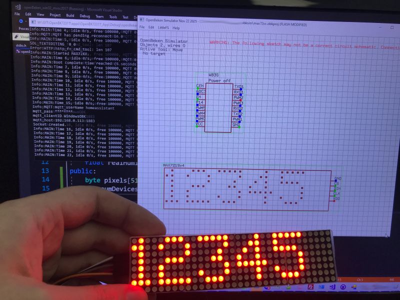
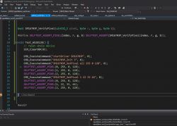
    I am adding WS2812B driver self-tests and soon I will include them in Simulator as well:
    Screenshot of Visual Studio with code testing the WS2812B driver.

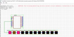
    Added after 1 [hours] 32 [minutes]:

    Screenshot of OpenBeken simulator showing the circuit schematic with WS2812B LEDs.

    Added after 36 [minutes]:

    Simulation of WS2812B wiring in OpenBeken Simulator with circuit schematic warning.
    Helpful post? Buy me a coffee.
  • ADVERTISEMENT
  • #8 21066564
    p.kaczmarek2
    Moderator Smart Home
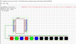
    I am working now on per-pixel LED animations:
    Circuit simulation with WS2812 LEDs in OpenBeken software.
    Helpful post? Buy me a coffee.
  • #9 21232905
    p.kaczmarek2
    Moderator Smart Home
    Simulator binaries should be now available in Releases, can anyone check if they are working?
    https://github.com/openshwprojects/OpenBK7231T_App/releases
    Helpful post? Buy me a coffee.
  • #10 21232919
    insmod
    Level 22  
    >>21232905 Haven't fully tested, but it starts and main page is working ok. v1.17.712
  • #11 21232931
    p.kaczmarek2
    Moderator Smart Home
    Next step is probably running self tests once on Github Actions to chęck for breaking changes in each commit
    Helpful post? Buy me a coffee.
  • #12 21233922
    p.kaczmarek2
    Moderator Smart Home
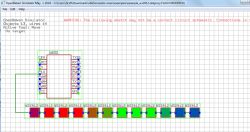
    @insmod @divadiow now self tests are run on Github, github action will fail if any of self tests fails.
    For example, the following test checks WS2812 API:
    Code: C / C++
    Log in, to see the code

    Now, if anyone changes the WS2812 API and breaks it, we will immediatelly know.
    Helpful post? Buy me a coffee.
  • #13 21233963
    divadiow
    Level 34  
    excellent.
    Not that burning fw is a chore, but it's also nice to be able to just run an exe to check main app changes in a PR quickly.
  • #14 21235813
    p.kaczmarek2
    Moderator Smart Home
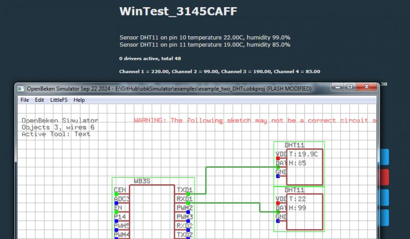
    Now virtual DHT11 has a "body", so there can be two or more of them:
    Screenshot from the OpenBeken simulator showing a test of two DHT11 sensors in a circuit.
    Helpful post? Buy me a coffee.
  • #15 21238382
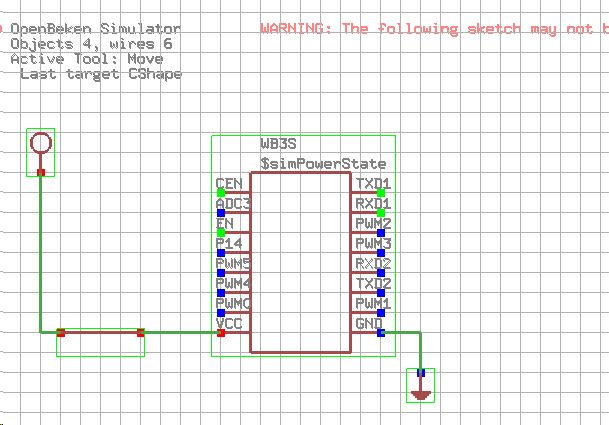
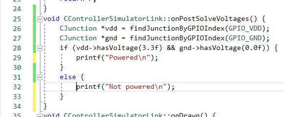
    p.kaczmarek2
    Moderator Smart Home
    Progress towards simulation of WiFi module power on and off...
    Circuit simulation diagram of a WiFi module in OpenBeken Simulator.

    Screenshot of source code in C++ language.
    Helpful post? Buy me a coffee.
  • #16 21330476
    p.kaczmarek2
    Moderator Smart Home
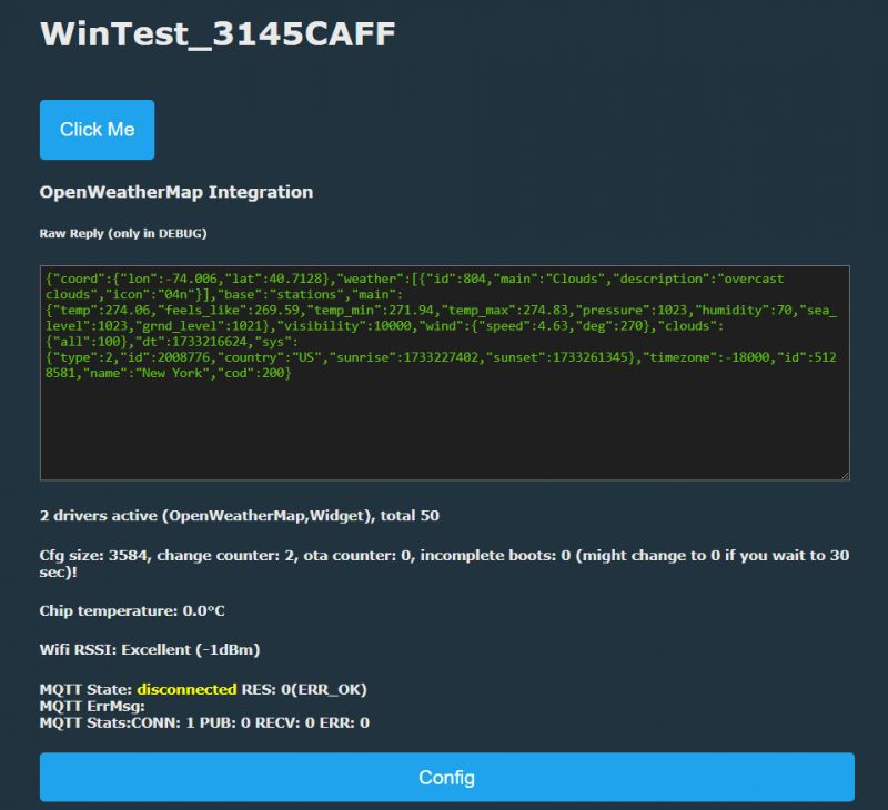
    I love this Simulator, I can test OpenWeatherMap integration on Windows, without flashing any device:
    Screenshot of a Windows simulator testing OpenWeatherMap integration.
    Helpful post? Buy me a coffee.
Topic summary

The OpenBeken IoT device simulator has been released in its first early alpha version for testing, allowing users to run a virtual OBK device for OBK scripting, MQTT setup, and Home Assistant integration. Users can create and save sketches in JSON format, simulate GPIO interactions with buttons and relays, and utilize a fully functional OBK HTTP panel on Windows. Feedback indicates successful operation on Windows 11, with ongoing development including self-tests for WS2812B driver and per-pixel LED animations. Users are exploring the potential for downloading templates from existing devices and the simulator's capabilities for simulating WiFi module power states.
Summary generated by the language model.
ADVERTISEMENT