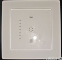
The Currysmarter Gen6 Wifi Courtain switch is a 55*55mm Modular Smart Curtain/Shutter switch. There is a 2 frame in glass available and Currysmarter has other switches in their program. I actually could put it in frames of the Gira 55 System.

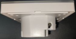
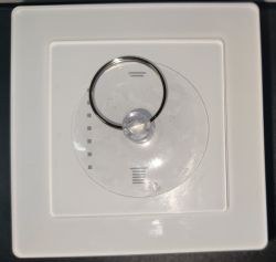
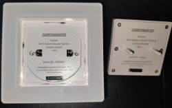
It has a glass frame/switch cover with touch pads for the up/stop/down functions. It is available in black and white color. Modular design means in this case that you have a Control Modul that contains the CBU Modul for smart communication and Power Modul where you plugin in the Control Modul. They sell each part of the modul separately in their shop. On Amazon you find the whole switch in single, two and four pieces packaging - each with different discounts and sometimes even special discounts so you get 4 of the switches for below 100EUR. Far cheaper than the VestaMatic RollTec Pro G/S that costs nowadays per piece 100EUR - thats one of my reasons for changing them all over the time although each Currysmarter is more complicated from the time investment for cloud cutting than actually expected since the only option seems to be to desolder the CBU from the Control Module completely. I tried to shutdown the MCU Chip CMS79FT738 but this is nearly a massacre and could end in a destruction of this module part of the device. To let you participate in my experience so you don't need to do this - I tried to disconnect the 3V VCC from the MCU... Didn't work the MCU still got enough power somehow. I disconnected the RX1 PIN - unsuccessful... Still the MCU interfered the communication. So finally I cut the RX1 PIN and was able to flash the MCU without desoldering the module. I was lucky enough - with a little soldering and some wires I could direclty connect the CBU Modules TX1/RX1 to the MCU TX1/RX1 PINs again and established with soldering the 3V VCC again. Module is alive and still working... Although I cannot recommend this to someone. Desoldering the CBU or just the MCU TX1/RX1 Pins are the better direction to go. Yes more work but far easier than actually expected before in regards for simply desoldering TX1 and RX1 at MCU and soldering both again after fashing...
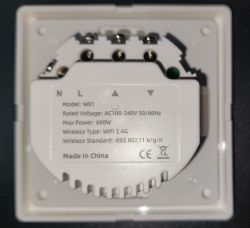
So here is the teardown of the Control Modul W01:
Separate the Control Modul from the Power Modul (simply by pulling it of with the help of the suction cup from the package)
Turn it around and unscrew the 6 screws, take out the PCB - careful not to loose parts of it (i.e. the rubber for LED Light centering). In my case I needed to press on the black connector a little and need to use some controlled force to take it out because the white plastic box and PCB are quite tight designed...
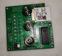
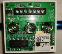
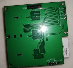
There are actually 3 way to do - first is to cut the MCU TX1 (Pin 10) and RX1 (Pin 9) and fix this later on by connecting wires of CBU TX to MCU RX and CBU RX to MCU TX. Works but really looks like patched or more like a massacre.
To desolder the CBU use the hints from the YouTube video from Elektroda.com channel: [youtube]https://www.youtube.com/watch?v=fSbeKwCCMHM [/youtube]
To just disconnect the MCU RX1 and TX1 while flashing get your hints from the Mr. Solderfix channel: [youtube]https://www.youtube.com/watch?v=U_g_yxLQeMg [/youtube]
I actually follow the Mr. Solderfix way - it is far easier for me than to desolder the CBU Module. This is build on experience I got from cutting and fixing connections and trying to desolder the CBU Module.
Before flashing, please check that MCU und CBU are really not connected on their TX1/RX1 - else reading and writing will fail, maybe even leaving the module in an unusable state. Connected afterward GND (Pin 13), 3V3 (Pin 14), TX1 (Pin 15), RX1 (Pin 16) to your USB TTL Device. CEN is on Pin 18. If you loose one of the TX1/RX1 MCU soldering pads - don't worry, just connect it directly to the MCU... It may happen because PCB is thin, the soldering pads are very heat critical, the place to work quite small and you only can desolder the pin once...
CBU Module is described here ( https://developer.tuya.com/en/docs/iot/cbu-module-datasheet?id=Ka07pykl5dk4u )
MCU Chip is described here ( https://www.mcu.com.cn/uploads/img1/tupian//%...8B%E8%BD%BD/CMS79F73x_User_Manual_V1.7%20.pdf )
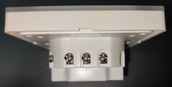
And here are some pictures of the Power Modul T01 (you don't need to open this part actually, so just for reference and because you don't need to open it to see the inside ):
):
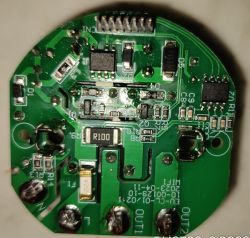
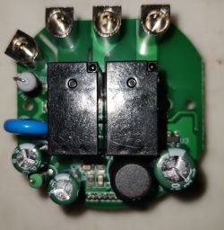
The main functions / DPIDs of the MCU were easy to find but the switch has some hidden function used for autocalibration. To find this I captured the communication using Realterm and take the captured data over to the Tuya MCU analyzer from Elektroda - voila DPID 3 is used for this and sending an enum 0 starts the autocalibration while 1 stopps it (so 1 actually maybe means device calibrated...).
I think I don't need to post the MCU Capturing data - Everything is unleashed in the MCU Logging and can be found in the autoexec.bat below. The Switch has abilities to lower the led power from high to low to off - but only by touching the Pause/Stop button at the switch itself. I didn't find a way to automate this somehow. There is no why by the Tuya App either... Same for the childlock - only by phyiscal access to the switch it can be enabled and disabled. I think the MCU Programming need to be changed to allow this... Unfortunately...
So here the device data for the beautiful database.
Here the /autoexec.bat for your enjoyment and convenience There are two autocalibration buttons defined. One sends the command by UART (needed after Switch reboot) and the other one by setChannel (works after doing the UART method once). No idea why - actually both should do the same...
Home Assistant configuration.yaml - device get autodiscovered by its backlight switch. The other two entities of the device I had to define via configuration.yaml .


It has a glass frame/switch cover with touch pads for the up/stop/down functions. It is available in black and white color. Modular design means in this case that you have a Control Modul that contains the CBU Modul for smart communication and Power Modul where you plugin in the Control Modul. They sell each part of the modul separately in their shop. On Amazon you find the whole switch in single, two and four pieces packaging - each with different discounts and sometimes even special discounts so you get 4 of the switches for below 100EUR. Far cheaper than the VestaMatic RollTec Pro G/S that costs nowadays per piece 100EUR
So here is the teardown of the Control Modul W01:
Separate the Control Modul from the Power Modul (simply by pulling it of with the help of the suction cup from the package)
Turn it around and unscrew the 6 screws, take out the PCB - careful not to loose parts of it (i.e. the rubber for LED Light centering). In my case I needed to press on the black connector a little and need to use some controlled force to take it out because the white plastic box and PCB are quite tight designed...


There are actually 3 way to do - first is to cut the MCU TX1 (Pin 10) and RX1 (Pin 9) and fix this later on by connecting wires of CBU TX to MCU RX and CBU RX to MCU TX. Works but really looks like patched or more like a massacre.
To desolder the CBU use the hints from the YouTube video from Elektroda.com channel: [youtube]https://www.youtube.com/watch?v=fSbeKwCCMHM [/youtube]
To just disconnect the MCU RX1 and TX1 while flashing get your hints from the Mr. Solderfix channel: [youtube]https://www.youtube.com/watch?v=U_g_yxLQeMg [/youtube]
I actually follow the Mr. Solderfix way - it is far easier for me than to desolder the CBU Module. This is build on experience I got from cutting and fixing connections and trying to desolder the CBU Module.
Before flashing, please check that MCU und CBU are really not connected on their TX1/RX1 - else reading and writing will fail, maybe even leaving the module in an unusable state. Connected afterward GND (Pin 13), 3V3 (Pin 14), TX1 (Pin 15), RX1 (Pin 16) to your USB TTL Device. CEN is on Pin 18. If you loose one of the TX1/RX1 MCU soldering pads - don't worry, just connect it directly to the MCU... It may happen because PCB is thin, the soldering pads are very heat critical, the place to work quite small and you only can desolder the pin once...
CBU Module is described here ( https://developer.tuya.com/en/docs/iot/cbu-module-datasheet?id=Ka07pykl5dk4u )
MCU Chip is described here ( https://www.mcu.com.cn/uploads/img1/tupian//%...8B%E8%BD%BD/CMS79F73x_User_Manual_V1.7%20.pdf )
And here are some pictures of the Power Modul T01 (you don't need to open this part actually, so just for reference and because you don't need to open it to see the inside


The main functions / DPIDs of the MCU were easy to find but the switch has some hidden function used for autocalibration. To find this I captured the communication using Realterm and take the captured data over to the Tuya MCU analyzer from Elektroda - voila DPID 3 is used for this and sending an enum 0 starts the autocalibration while 1 stopps it (so 1 actually maybe means device calibrated...).
I think I don't need to post the MCU Capturing data - Everything is unleashed in the MCU Logging and can be found in the autoexec.bat below. The Switch has abilities to lower the led power from high to low to off - but only by touching the Pause/Stop button at the switch itself. I didn't find a way to automate this somehow. There is no why by the Tuya App either... Same for the childlock - only by phyiscal access to the switch it can be enabled and disabled. I think the MCU Programming need to be changed to allow this... Unfortunately...
So here the device data for the beautiful database.
{
  "vendor": "Currysmarter",
  "bDetailed": "0",
  "name": "Currysmarter WLAN Switch",
  "model": "6Gen",
  "chip": "BK7231N",
  "board": "EU-CL-01/02-2 10-00130-10 2023-3-3",
  "flags": "1024",
  "keywords": [
    "currysmarter",
    "gen6",
    "shutter",
    "curtain",
    "MCU",
    "CBU",
    "CMS79FT738"
  ],
  "pins": {},
  "command": "",
  "image": "https://obrazki.elektroda.pl/9077436000_1712324125.jpg",
  "wiki": "https://www.elektroda.com/rtvforum/viewtopic.php?p=21033819#21033819"
}
Here the /autoexec.bat for your enjoyment and convenience
# Administrativ stuff first...
PowerSave 1
# Replace 0.0.0.0 with your NTP Server IP Address
startDriver NTP
ntp_setServer 0.0.0.0

# Yeah - it is an MCU in the CurrySmarter Gen6 WiFi Switch.
startDriver TuyaMCU
tuyaMcu_defWiFiState 4
tuyaMcu_setBaudRate 9600

# Wouldn't it be nice to have a custom element for this?
# Some Up/Stop/Down style element would be great ;-)
setChannelType 1 textfield
setChannelLabel 1 "Touch buttons (0=Open 1=Stop 2=Close)"
setChannelVisible 1 false
linkTuyaMCUOutputToChannel 1 4 1

# Wouldn't it be nice to have a custom element for this?
# Some slider and some text input for values between 0 and 100 would be nice...
setChannelType 2 textfield
setChannelLabel 2 "Percentage"
linkTuyaMCUOutputToChannel 2 2 2

setChannelType 3 textfield
setChannelLabel 3 "Autocalibrate (0=Start)"
setChannelVisible 3 false
linkTuyaMCUOutputToChannel 3 4 3

setChannelType 7 toggle
setChannelLabel 7 "Light On/Off"
linkTuyaMCUOutputToChannel 7 1 7

# Wouldn't it be nice to have a custom element for this?
# Some ComboBox/Select to choose values of a list in value=text format...
setChannelType 8 textfield
setChannelLabel 8 "Percent change direction (0=Motor Reverse, 1=Default Steering)"
linkTuyaMCUOutputToChannel 8 4 8
setChannelVisible 8 false

# Let's create some buttons for different functions. Typing everything in Textfields and send it is uncool.
startDriver httpButtons

setButtonEnabled 0 1
setButtonColor 0 "#2596be"
setButtonLabel 0 "Up/Open"
setButtonCommand 0 "setChannel 1 0"

setButtonEnabled 1 1
setButtonColor 1 "#abdbe3"
setButtonLabel 1 "Stop/Pause"
setButtonCommand 1 "setChannel 1 1"

setButtonEnabled 2 1
setButtonColor 2 "#2596be"
setButtonLabel 2 "Down/Close"
setButtonCommand 2 "setChannel 1 2"

setButtonEnabled 3 1
setButtonColor 3 "#bdbaba"
setButtonLabel 3 "% bar dir. (Motor Reverse)"
setButtonCommand 3 "setChannel 8 0"

setButtonEnabled 4 1
setButtonColor 4 "#bdbaba"
setButtonLabel 4 "% bar dir. (Default Steering)"
setButtonCommand 4 "setChannel 8 1"

setButtonEnabled 5 1
setButtonColor 5 "#F90101"
setButtonLabel 5 "Start Autocalibration uart"
setButtonCommand 5 "uartSendHex 55AA00060005030400010012"

setButtonEnabled 6 1
setButtonColor 6 "#F90101"
setButtonLabel 6 "Start Autocalibration setChannel"
setButtonCommand 6 "setChannel 3 0"
Home Assistant configuration.yaml - device get autodiscovered by its backlight switch. The other two entities of the device I had to define via configuration.yaml .
mqtt:
  - switch:
      unique_id: "OpenBK7231N_E196F5B0_autocalibrate"
      device:
        identifiers: "OpenBK7231N_E196F5B0"
        configuration_url: "http://deviceipordnsname/index"
        manufacturer: "Beken Corporation"
        model: "BK7231N"
      name: "Autocalibrate"
      state_topic: "obkE196F5B0/3/get"
      command_topic: "obkE196F5B0/3/set"
      qos: 1
      payload_on: 0
      payload_off: 1
      retain: true
      availability:
        - topic: "obkE196F5B0/connected"
  - cover:
      unique_id: "OpenBK7231N_E196F5B0_position"
      device:
        identifiers: "OpenBK7231N_E196F5B0"
        configuration_url: "http://deviceipordnsname/index"
        manufacturer: "Beken Corporation"
        model: "BK7231N"
      name: "Position"
      command_topic: "obkE196F5B0/1/set"
      state_topic: "obkE196F5B0/1/get"
      position_topic: "obkE196F5B0/2/get"
      set_position_topic: "obkE196F5B0/2/set"
      payload_open:  "0"
      payload_close: "2"
      payload_stop:  "1"
      state_opening: "open"
      state_closing: "close"
      state_stopped: "stop"
      optimistic: false
      retain: true
      availability:
        - topic: "obkE196F5B0/connected"
      position_template: |-
        {% if not state_attr(entity_id, "current_position") %}
          {{ value }}
        {% elif state_attr(entity_id, "current_position") < (value | int) %}
          {{ (value | int + 1) }}
        {% elif state_attr(entity_id, "current_position") > (value | int) %}
          {{ (value | int - 1) }}
        {% else %}
          {{ value }}
        {% endif %}


