logo elektroda
logo elektroda
X
logo elektroda

Can the ERC2202-W Kinetic Switch with WBR2 Module Be Flashed with Custom Firmware?

rchristescu 1173 4
ADVERTISEMENT
  • #1 21046382
    rchristescu
    Level 7  

    I have just bought a kinetic switch ERC2202-W from here:
    https://www.emag.ro/releu-smart-rovo-kinetic-...-2x5a-wifi-rf433-tuya-erc2202-w/pd/DSTPK2YBM/
    Product page of Smart Rovo ERC2202-W on eMAG.

    It looks exactly as the one from this topic:
    https://www.elektroda.com/rtvforum/topic3989088.html#20651842
    But after opening it, I saw it has a different wifi module, WBR2 instead of CB2S.
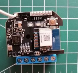
    Electronic module with components and WBR2 marking.
    I checked and I found on this page:
    https://www.elektroda.com/rtvforum/topic4022927.html#20869253
    that WBR2 has a W701-VA2-C chip.
    Is any possibility to flash a custom firmware?
  • ADVERTISEMENT
  • Helpful post
    #2 21046554
    p.kaczmarek2
    Moderator Smart Home
    I have it on my TODO list, but currently it's not complete. This is a Realtek flavour, as far as I know. I'll ping you once it's ready.

    UPDATE 2025 New guide for those WBR3 chips:
    WBR2, WBR3, WBRU, W701-VA2-CG pinout, datasheet, flashing for Home Assistant
    Helpful post? Buy me a coffee.
  • ADVERTISEMENT
  • #3 21081589
    lechm56
    Moderator
    Unlocked at the request of the author.
  • ADVERTISEMENT
  • #4 21081891
    rchristescu
    Level 7  

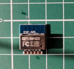
    Till Realtek chip will be supported by a custom firmware, I have ordered few ESP-02s to try the brain transplant method.
    ESP-02S module on a green cutting mat.
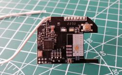
    I have desoldered the original module WBR2 and cleaned the PCB.
    The image shows a PCB with soldered wires.
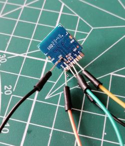
    Then, solder jumper wires to 3V3, GND, RX, TX and GPIO0 onto ESP-02s module and flash Tasmota.
    Close-up of an ESP-02s module with soldered wires.
    Configure as Tuya MCU (54) with GPIO1 as Tuya Tx and GPIO3 as Tuya Rx.
    {"NAME":"Kinetic Switch","GPIO":[0,2272,0,2304,0,0,0,0,0,0,0,0,0,0],"FLAG":0,"BASE":54}

    Additionally, the command
    Backlog TuyaMCU 11,1; TuyaMCU 12,2
    will activate both channels.
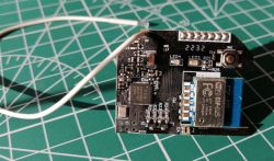
    Desolder the wires from ESP-02s, clean and solder onto PCB.
    ESP-02s module soldered onto a PCB.
    That's it, assemble the device and it is fully functional. I control it with OpenHab via MQTT.

    Final note:
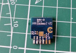
    I have 6 devices with WBR2, I will replace the module with ESP-02s for 4 of them and keep 2 devices for when a custom firmware will be available for Realtek W701-VA2-C chip. Even then, if there will be not an OTA solution, the module will have to be removed, flashed and soldered back because all relevant pads for UART flashing are on the back side.
    Top side of the WBR2 module with visible markings and solder pads.
ADVERTISEMENT