logo elektroda
logo elektroda
X
logo elektroda

[Youtube] WBR2/WBR3 - RTL8720CF flashing step by step guide/tutorial - how to solder and flash

p.kaczmarek2 2178 13
ADVERTISEMENT
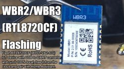
  • WBR3 module from the RTL8720CF series with text about the flashing process.
    RTL8720CF/W701-VA2-CG can be easily flashed just like ESP modules - you just need to connect few more wires. Here's a step by step video showing firmware change process for WBR3 and WBR2 modules, which are using mentioned Realtek chip. This way you can free your devices from the cloud and pair them with Home Assistant.

    This guide is applicable to the following modules with the core chip of RTL8720CF or similar, so: WBR1, WBR2, WBR3, WBR2L, WBR3L, WBRU etc.

    See full guide:


    After finishing the guide, you can do the configuration futher like on our other videos on the playlist:
    https://www.youtube.com/watch?v=pkcspey25V4&a...LzbXEc2ebpH0I8m_Cfbqv1MTlQuBKYvlx&index=2

    If you want to see the same guide in text format, please see:
    - English Guide
    - Polish Guide

    Thank you for watching! Let us know how the flashing process went. You can also visit our teardowns list here: https://openbekeniot.github.io/webapp/devicesList.html , if you have a device that's not listed yet, please consider submitting it. See you!

    Cool? Ranking DIY
    Helpful post? Buy me a coffee.
    About Author
    p.kaczmarek2
    Moderator Smart Home
    Offline 
    p.kaczmarek2 wrote 11841 posts with rating 9935, helped 566 times. Been with us since 2014 year.
  • ADVERTISEMENT
  • #2 21427090
    divadiow
    Level 34  
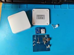
    a user on this forum kindly sent me some WBR3 modules for testing. The location of those pads on the rear is a pain, as already stated.

    I think I will turn the CR3L Bluetooth Gateway chassis into a WBR3-type dev board. Similar to your NodeMCU hack here https://www.elektroda.com/rtvforum/topic4097185.html#21375394 and other NodeMCU/NiceMCU conversions

    https://www.elektroda.com/rtvforum/topic3973321.html
    https://www.elektroda.com/rtvforum/topic4095663.html

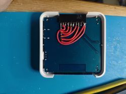
    With the CR3L removed, and unlikely to return, for testing in other adaptors I think a series of jumper headers could easily be routed to the case for easy-access testing of all available GPIOs on this module. Any ugly routing of pads on the rear of the module will be hidden inside.

    Disassembled Smart Gateway with WBR3 modules on a blue mat.
  • #3 21427247
    p.kaczmarek2
    Moderator Smart Home
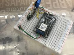
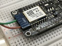
    Will you route out the pad on the module back? I did it, just to be on the safe side - it may be needed if I brick the OTA.

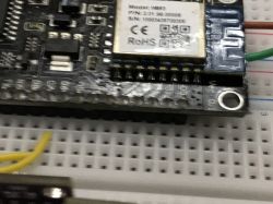
    Electronic module placed on a breadboard with connected wires.
    Electronic module on a breadboard with soldered wires.
    Electronic module placed on a breadboard.
    Helpful post? Buy me a coffee.
  • #4 21427250
    divadiow
    Level 34  
    yes. initial idea is that all should be routed to the outside case for every eventuality
  • ADVERTISEMENT
  • #5 21427264
    p.kaczmarek2
    Moderator Smart Home
    So you have two options:
    1. do just like me, route out a wire
    2. is this just a twosided board and copper ground pour is on both sides onder WBR3 place? If so, maybe you could... well, carefully cut the board under it to expose the required pad? Still ,it may not be the best idea
    Helpful post? Buy me a coffee.
  • ADVERTISEMENT
  • #6 21427272
    divadiow
    Level 34  
    Quote:
    So you have two options:
    1. do just like me, route out a wire


    likely this, but maybe with thin enamelled wire

    Quote:
    2. is this just a twosided board and copper ground pour is on both sides onder WBR3 place? If so, maybe you could... well, carefully cut the board under it to expose the required pad? Still ,it may not be the best idea


    hadn't thought of this, but it looks like most of both sides are covered by a ground plane so that would need careful avoidance/isolation from the soldered pads.
  • ADVERTISEMENT
  • #7 21427346
    p.kaczmarek2
    Moderator Smart Home
    The PCB edges would be needed to be sanded with sand paper.

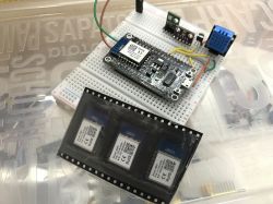
    Btw, I still have those 3 from the reader:
    Close-up of a PCB prototype with electronic components on a breadboard.
    I will probably swap them for ESP soon. One of my switches is still TYWE3S-based, but soon it will run on Realtek. We just first need to make sure that it runs stable enough for wall placement.

    Do you have HA instance running?
    Helpful post? Buy me a coffee.
  • #8 21428230
    divadiow
    Level 34  
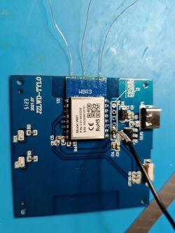
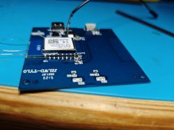
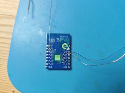
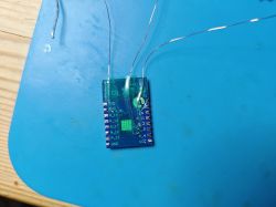
    some progress
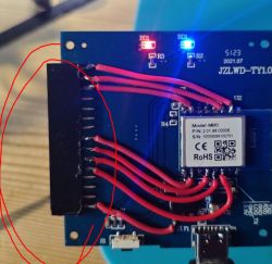
    Blue printed circuit board with connected wires on a blue work mat. Circuit board with attached wires on a blue mat. Circuit board with WBR3 module on a blue background.Close-up of a blue PCB with an electronic module and connected wires.

    Added after 8 [hours] 42 [minutes]:

    p.kaczmarek2 wrote:
    Do you have HA instance running?

    yes. not prod setup, just testing


    Screenshot of Home Assistant interface showing various devices and their status.
  • #9 21430141
    divadiow
    Level 34  
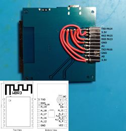
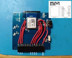
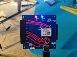
    Image of a circuit board with red wires connected to pins labeled as TX0 PA14, 3.3V, RX2 PA15, RX0 PA13, GND, A1, TX2 PA16, GND, A0, 3.3V. PCB board with WBR3 module and USB-C connector with labeled components.

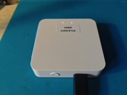
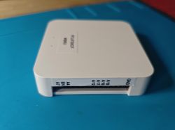
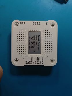
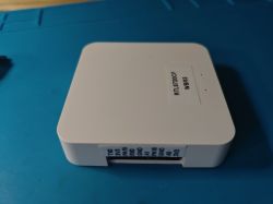
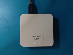
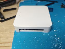
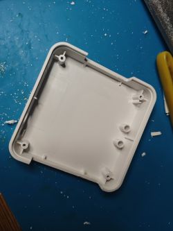
    White electronic device with two LEDs on top, one red and one blue, and a button on the side. Plastic enclosure of a device with pin labels on the side. View of the Smart Gateway TYBL1 device from the bottom, with port labels and power indication. Electronic module with port and model labels on a white casing. White electronic module RTL8720CF WBR3 with connected USB-C cable on a blue background. White plastic DIY project case with visible cutouts for ports and connectors. Printed circuit board with connected red wires in a white case. Empty plastic enclosure on a blue surface with a tool on the right. Circuit board with red and blue LEDs, button, and wired connections.

    and now A0 and A13 can be pulled high with ease
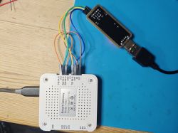
    Electronic device with wires connected to a USB adapter.

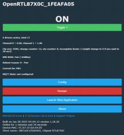
    and flashed to OpenRTL

    PA3 - red LED
    PA2 - blue LED
    PA11 - button

    OpenRTL control panel with active mode

    nice 5v USB-C, easy flashing, spare GPIOs, labelled, multiple grounds and 3v3, spare headers for expansion :)
  • #10 21430151
    p.kaczmarek2
    Moderator Smart Home
    Very nice idea. Remember to add more grounds and VDD pins in advance.

    Also, we really need to check if it 's possible to print pin names on paper, it would help a lot if we could label this connector.
    Helpful post? Buy me a coffee.
  • #11 21430457
    divadiow
    Level 34  
    p.kaczmarek2 wrote:
    Very nice idea. Remember to add more grounds and VDD pins in advance.

    oh. I thought 3 GND and 2 3V3 would do for now. Plenty of space if more needed though

    Added after 45 [seconds]:

    p.kaczmarek2 wrote:
    it would help a lot if we could label this connector.

    which connector?
  • #12 21430463
    p.kaczmarek2
    Moderator Smart Home
    This one obviously:
    Close-up of a circuit board with an electronic module and red wires.
    I need to do the same for my dev board: https://www.elektroda.com/rtvforum/topic4062695.html
    Helpful post? Buy me a coffee.
  • #14 21430484
    p.kaczmarek2
    Moderator Smart Home
    Ah right, sorry, I didn't see. It seems that we need to use "big thumb" image option more often.
    Helpful post? Buy me a coffee.
Topic summary

The discussion revolves around flashing the RTL8720CF chip used in WBR2 and WBR3 modules, similar to ESP modules. Users share experiences and techniques for modifying the modules, including routing wires for easier access to GPIOs and ensuring stable operation for integration with Home Assistant. Various methods for exposing pads on the module for flashing are debated, including careful PCB modifications. Users also discuss the importance of labeling connections and ensuring adequate power and ground connections for development purposes.
Summary generated by the language model.
ADVERTISEMENT