I recently bought few ERC309 kinematic relays and switches.
Relay: https://www.rovo.ro/produse-smart/releu-rovo-erc309-kinetic-1-canal-5a-wifi-rf433-tuya.html
Switch: https://www.vonmag.ro/produse/info/es2154-pre...6emeWXD--N5MyjGiiAk4gMZ_FcufOVxcaAiAmEALw_wcB
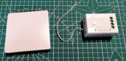
I like that the switch does not require any power, battery or wires.
Before buying them, I checked that they are supported by Tasmota.
https://templates.blakadder.com/ERC309.html
However, after receiving them and disassemble the first one, I get a big surprise. There is not ESP8266 inside anymore, TYWE3S has been replaced by CB3S.
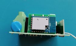
The housing is two parts, fixed together by 7 clips. Not so easy to open without small scratches (for me at least), but doesn't matter, the relay is supposed to be hidden anyhow.
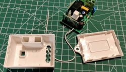
So, no ESP means no Tasmota, that means no Openhab (I don't use Home Assistant). After first disappointment, I start to search and I found two methods to solve the issue.
Method 1 - Brain transplant
I used the great tutorial from @blakadder: https://blakadder.com/replace-tuya-esp12/
I take out the wifi pcb, replaced the CB3S with an ESP12F flashed with Tasmota, then solder back the wifi pcb.
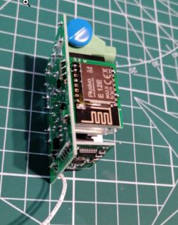
Template: {"NAME":"Kinetic Switch","GPIO":[1,2272,1,2304,1,1,0,0,1,1,1,1,1,0],"FLAG":0,"BASE":54}
It works like a charm!
Method 2 - OpenBeken
After using method 1 for 3 relays, I accidentally found this site and the OpenBeken project. Thanks a lot for this great firmware!
So, I take out the wifi pcb, flash the CB3S using BK7231Flasher.exe, connect to device AP and make some basic configurations (wifi, names, mqtt). Then solder back the wifi pcb and connect to mains power.
For the module configuration I got some inspiration from this topic:
https://www.elektroda.com/rtvforum/topic3898502.html
So I create a file autoexec.bat with the following content:
and upload the file using Web Application.
After manually restarting the device, it works perfectly!
JSON template:
One small final note: With original firmware, as well with Tasmota, the red led follow the relay (led on when relay is on and led off when relay is off). With OBK, the led blink one time about 1ms when relay become on, all the rest it is off, except when starting, it blinks till connecting to wifi. For me this is not important at all because the relays will not be visible, but I am just curious why this different behavior. I have some experience with Tasmota but I am pretty new to OBK.
Relay: https://www.rovo.ro/produse-smart/releu-rovo-erc309-kinetic-1-canal-5a-wifi-rf433-tuya.html
Switch: https://www.vonmag.ro/produse/info/es2154-pre...6emeWXD--N5MyjGiiAk4gMZ_FcufOVxcaAiAmEALw_wcB

I like that the switch does not require any power, battery or wires.
Before buying them, I checked that they are supported by Tasmota.
https://templates.blakadder.com/ERC309.html
However, after receiving them and disassemble the first one, I get a big surprise. There is not ESP8266 inside anymore, TYWE3S has been replaced by CB3S.

The housing is two parts, fixed together by 7 clips. Not so easy to open without small scratches (for me at least), but doesn't matter, the relay is supposed to be hidden anyhow.

So, no ESP means no Tasmota, that means no Openhab (I don't use Home Assistant). After first disappointment, I start to search and I found two methods to solve the issue.
Method 1 - Brain transplant
I used the great tutorial from @blakadder: https://blakadder.com/replace-tuya-esp12/
I take out the wifi pcb, replaced the CB3S with an ESP12F flashed with Tasmota, then solder back the wifi pcb.

Template: {"NAME":"Kinetic Switch","GPIO":[1,2272,1,2304,1,1,0,0,1,1,1,1,1,0],"FLAG":0,"BASE":54}
It works like a charm!
Method 2 - OpenBeken
After using method 1 for 3 relays, I accidentally found this site and the OpenBeken project. Thanks a lot for this great firmware!
So, I take out the wifi pcb, flash the CB3S using BK7231Flasher.exe, connect to device AP and make some basic configurations (wifi, names, mqtt). Then solder back the wifi pcb and connect to mains power.
For the module configuration I got some inspiration from this topic:
https://www.elektroda.com/rtvforum/topic3898502.html
So I create a file autoexec.bat with the following content:
startDriver TuyaMCU
setChannelType 1 toggle
linkTuyaMCUOutputToChannel 1 1 1
and upload the file using Web Application.
After manually restarting the device, it works perfectly!
JSON template:
Code: JSON
One small final note: With original firmware, as well with Tasmota, the red led follow the relay (led on when relay is on and led off when relay is off). With OBK, the led blink one time about 1ms when relay become on, all the rest it is off, except when starting, it blinks till connecting to wifi. For me this is not important at all because the relays will not be visible, but I am just curious why this different behavior. I have some experience with Tasmota but I am pretty new to OBK.


