logo elektroda
logo elektroda
X
logo elektroda

Understanding the Aubess FS-02HW Mini Smart Switch: A Detailed Look at Chip CB2S BL2028N

Weafyr 4314 20
ADVERTISEMENT
  • #1 20595227
    Weafyr
    Level 4  
    Hi there,

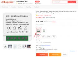
    I have got yet another Aubess switch version.
    Brand: Aubess
    Model: FS-02HW
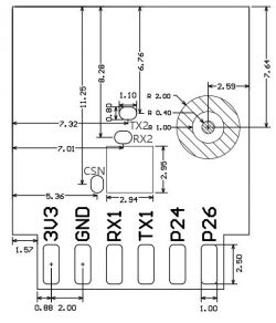
    Chip: CB2S (BL2028N)

    This is the listing where I bought it: https://www.aliexpress.com/item/1005004791531463.html
    Understanding the Aubess FS-02HW Mini Smart Switch: A Detailed Look at Chip CB2S BL2028N

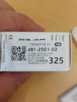
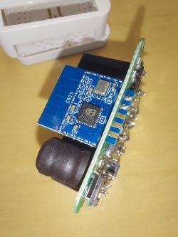
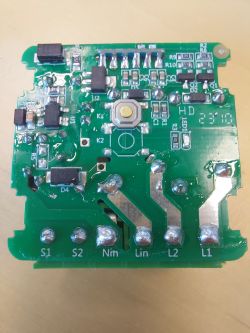
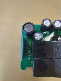
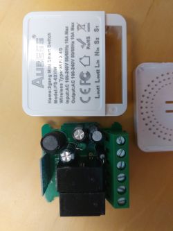
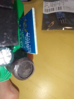
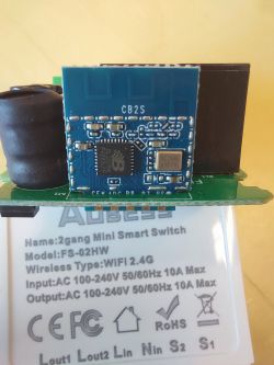
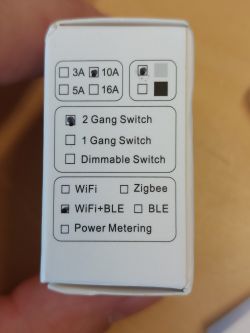
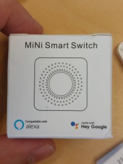
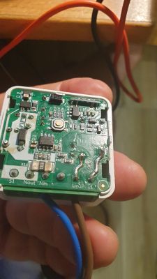
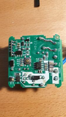
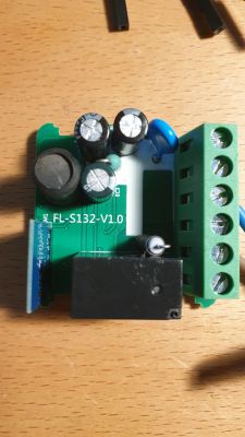
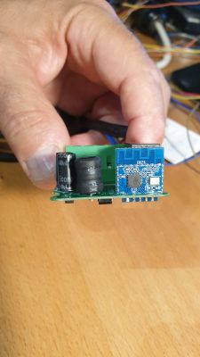
    Teardown photos:
    Understanding the Aubess FS-02HW Mini Smart Switch: A Detailed Look at Chip CB2S BL2028N Understanding the Aubess FS-02HW Mini Smart Switch: A Detailed Look at Chip CB2S BL2028N Understanding the Aubess FS-02HW Mini Smart Switch: A Detailed Look at Chip CB2S BL2028N Understanding the Aubess FS-02HW Mini Smart Switch: A Detailed Look at Chip CB2S BL2028N Understanding the Aubess FS-02HW Mini Smart Switch: A Detailed Look at Chip CB2S BL2028N Understanding the Aubess FS-02HW Mini Smart Switch: A Detailed Look at Chip CB2S BL2028N Understanding the Aubess FS-02HW Mini Smart Switch: A Detailed Look at Chip CB2S BL2028N Understanding the Aubess FS-02HW Mini Smart Switch: A Detailed Look at Chip CB2S BL2028N Understanding the Aubess FS-02HW Mini Smart Switch: A Detailed Look at Chip CB2S BL2028N

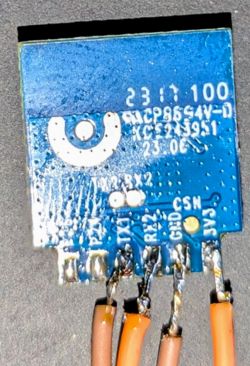
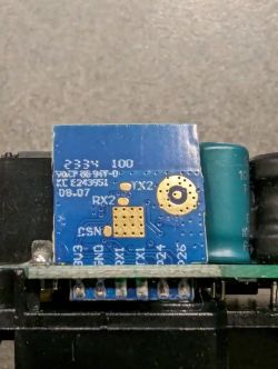
    So far this is where I end now. I am getting confused because according to labeling on the chip, there seems to be 2 "RX2" pins, and I need an advice how to proceed further with firmware flashing.
    Understanding the Aubess FS-02HW Mini Smart Switch: A Detailed Look at Chip CB2S BL2028N
  • ADVERTISEMENT
  • #2 20595325
    p.kaczmarek2
    Moderator Smart Home
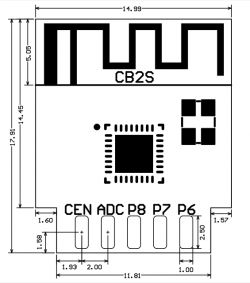
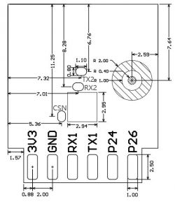
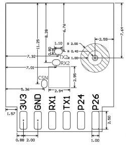
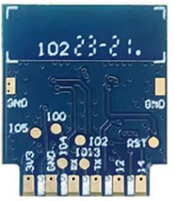
    Hello, the second RX2 (that in place of RX1) is a silkscreen error. Please see the image from Tuya docs.
    Understanding the Aubess FS-02HW Mini Smart Switch: A Detailed Look at Chip CB2S BL2028N
    Understanding the Aubess FS-02HW Mini Smart Switch: A Detailed Look at Chip CB2S BL2028N
    For flashing, we are using RX1 and TX1, not RX2/TX2 pair. UART2 is for debug log output at 115200.
    Please get latest version of our flasher, which can also extract GPIO config from 2MB backup binary:
    https://github.com/openshwprojects/BK7231GUIFlashTool
    Please watch our CB2S flashing video to see the whole process:


    You can see schematic at around 3:25 or so.

    I will also add that I already had seen myself a CB2S with mixed pad markings. It's just a production error. My one had silkscreen order swapped. The correct pinout is always at the Tuya site.
    Helpful post? Buy me a coffee.
  • ADVERTISEMENT
  • #3 20600738
    Weafyr
    Level 4  
    Thanks, but so far no luck on this one.
    I'm not able to flash or read the device. First I tried to solder wires directly on the device, when that didn't work I did take out CB2S out of the device but results were the same..
    I tried both restart and CEN short mode, nothing..
    I even connected to UART2 for debug, but it's only a stream of nothing.. When CEN is shorted the stream from UART2 will stop.
    Understanding the Aubess FS-02HW Mini Smart Switch: A Detailed Look at Chip CB2S BL2028N
    Don't know what to try next..

    Edit: Just flashed CBU successfully with the same setup...
  • #4 20625070
    fabcia
    Level 3  

    Hi, I have the same problem with a similar module FS-02WE (same model but with an energy monitor). No load or backup firmware. I tried with different adapters, different PCs, and different tools (app or Python). I don't understand if you solved the problem and loaded the firmware in CB2S (BL2028N chip). If yes, can you help me? Thanks in advance.
  • #5 20639165
    fabcia
    Level 3  
    Hi, my sensor is a little different. my model is fs-02WE (power meter and switch on neutral line) see the photo Understanding the Aubess FS-02HW Mini Smart Switch: A Detailed Look at Chip CB2S BL2028N Understanding the Aubess FS-02HW Mini Smart Switch: A Detailed Look at Chip CB2S BL2028N Understanding the Aubess FS-02HW Mini Smart Switch: A Detailed Look at Chip CB2S BL2028N Understanding the Aubess FS-02HW Mini Smart Switch: A Detailed Look at Chip CB2S BL2028N Understanding the Aubess FS-02HW Mini Smart Switch: A Detailed Look at Chip CB2S BL2028N Understanding the Aubess FS-02HW Mini Smart Switch: A Detailed Look at Chip CB2S BL2028N

    Cb2s module not have uart communication with BL0937 (power meter chip). No solder or contact between rx tx pin in Cb2s module and other part of sensor. I think that non-bootloader firmware loaded in BL2028N (cb2s chip) and then no possible charge firmware with uart interface. The module works well with original firmware and tuya environment (tested in app and tuya iot cloud platform).
    I think also that only solution is load firmware in spi mode but c22s module don't have contact for this (it's too hard solder in BL2028N chip directly.)
    @p.kaczmarek2 There is another way to flash the openbeken firmware in my cb2s? or only solution is transplant it with esp8266 module and tasmota firmware?
    thanks in advance
  • #6 20639185
    p.kaczmarek2
    Moderator Smart Home

    It looks like you have confused BL0942 with BL0937.
    BL0942 can be used in UART or SPI mode. It is usually connected to the RX/TX pin of BK7231.
    BL0937 is not a UART device. It can use any 3 GPIO as SEL, CF, and CF1. There is no need for contact with RX/TX.

    Furthermore, your CB2S has standard pads, so there is no problem with flashing:
    Understanding the Aubess FS-02HW Mini Smart Switch: A Detailed Look at Chip CB2S BL2028N
    Please follow this guide step by step to get your CB2S flashed:


    Make sure you have a 2MB backup so we can extract the GPIO template from it.
    Helpful post? Buy me a coffee.
  • #7 20639729
    fabcia
    Level 3  

    Hi @p.kaczmarek2, I'm sorry but I didn't explain my problem well. I have a WiFi smart switch and power meter called FS-02WE.
    1. The device works fine in the Tuya environment.
    2. The device has a BL0937 chip (power meter) and a c2bs module with BL2028N chip (Belon version of BK7231N).
    3. I know that the BL0937 chip doesn't communicate on the serial port with c2bs.
    4. I unsoldered the module and tried to load/backup firmware as shown in the video, but the module is not recognized by the OpenBK7231T_App application.
    5. I have already uploaded the signature to other c2bs or c3bs modules successfully.

    I think that in the c2bs module (BL2028N), the manufacturer has not loaded the bootstrap firmware address from 0x00000000 to 0x11000 //68KB, and then the serial port is not functional (the chip does not use serial communication for operation, and the manufacturer has not loaded bootstrap firmware for UART communication).

    If my guess is right, it is not possible to load the firmware with serial communication. Another way is to upload the firmware through SPI, but the c2bs module has no pins for that, and soldering the connections on the chip is too hard for me.

    May you tell me if my assumption is correct? (If yes) Do you know another procedure to load the firmware? Is the only solution to transplant the c2bs module with an ESP8266 module?

    Thanks in advance,
    F
  • #8 20639767
    p.kaczmarek2
    Moderator Smart Home

    To the best of my knowledge, BL2028N is flashable, as seen here:
    https://www.elektroda.com/rtvforum/topic3930515.html
    You just need to flash it as BK7231N (not BK7231T). Is it different in your case?

    If it really has a different bootloader, then maybe you really will have to transplant for ESP. But first, can you show me the UART log from the TX2 pin of the said module? I would like to see how it identifies, which SDK version, etc.
    Helpful post? Buy me a coffee.
  • #9 20641594
    Weafyr
    Level 4  

    Weafyr wrote:
    I'm not able to flash or read the device. First, I tried to solder wires directly onto the device. When that didn't work, I did take out CB2S out of the device but the results were the same.
    I tried both restart and CEN short mode, but nothing worked.
    I even connected to UART2 for debugging, but it's only a stream of nothing. When CEN is shorted, the stream from UART2 will stop.

    I don't know what to try next..


    As I wrote before, I have connected the UART2 of the device and I got no useful output.
  • ADVERTISEMENT
  • #10 20642343
    fabcia
    Level 3  

    @p.kaczmarek2
    The TX2 log is:
    at 11500 baud
    F8 F0 FF F0 FF FF FE FF E0 00 3F 10 FF 10 00 00 00 00 00 00 00 00 00 00 00 00 00 00 00 00 00 40 00 00 00 00 00 00 00 00 00 FE 22 FF E0 FF 1E 1E E0 FC 0F 1C 00 C0 80 CC 08 0C FC FC 0F 07 0F 84 84 00 0C 0F C0 FF 07 80 00 03 C0 00 00 80 80 A1 32 FE C0 FF 1F F8
    at 9600 baud
    FF 00 00 FF FF 00 00
    TX2 writes only on power on and changes every power on. (in ASCII mode only rubbish)
    Any ideas?
  • #11 21085368
    Pete0815
    Level 7  

    Hi

    Thanks and I'm testing and learning with some FS-02HW at the moment.

    Exchanging the CB2S with an ESP02S and configuring your pin configuration works great. But like to get a little bit more advanced with openbeken and totally struggling to flash. Used flasher version 1.1.6 and had a success with a desoldered CB2S some days ago but could not 100% remember how I did it.

    This time tried to flash keeping the CB2S inside of the device and getting no bus signal. But with a desoldered CB2S it is same this time.
    Because timing of CEN seems to be critical I used power on/off method without success.

    Tested CP2102 converter and CH340 with AMS1117 to avoid that 3.3V is not stable.

    Kindly ask for your hints because cannot flash CB2S at all at the moment and sorry for this very general question and of course checked the wiring and watched the youtube video guide.

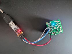
    Thanks USB UART adapter connected to a circuit board with glowing LEDs
  • #12 21086320
    p.kaczmarek2
    Moderator Smart Home
    So are you flashing with CB2S desoldered or not? The photo is showing CB2S in circuit , without desoldering.

    Futhermore, are you really sure that this USB to UART converter can provide enough current?

    I dont use CEN method, I am usually doing:
    1. desolder CB2S
    2. connect rx, tx, 3.3V, gnd
    3. disconnect 3.3V from CB2S
    4. start flashing
    5. optionally. temporarily, short the 3.3V wire from CB2S (not from power supply !!) to ground
    6. connect back wire 3.3V from CB2S to power supply
    7. flashing should start...
    Helpful post? Buy me a coffee.
  • #13 21086451
    Pete0815
    Level 7  

    p.kaczmarek2 wrote:
    So are you flashing with CB2S desoldered or not? The photo is showing CB2S in circuit, without desoldering.


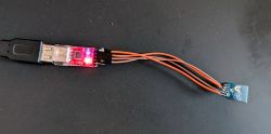
    Both. I have several CB2S and tried soldered/desoldered 2 different converters but no bus signal is detected.
    USB-RS232 converter with red LED lighting connected via wires to a small circuit board.

    p.kaczmarek2 wrote:

    Furthermore, are you really sure that this USB to UART converter can provide enough current?

    No because I don´t know the power requirements from converter + circuit. In the circuit I also see an AMS1117 as same on the converter but cannot be sure and therefore also tested desoldered and 2 converters but no success

    p.kaczmarek2 wrote:

    I don't use CEN method, I am usually doing:
    1. desolder CB2S
    2. connect rx, tx, 3.3V, gnd
    3. disconnect 3.3V from CB2S
    4. start flashing
    5. optionally. temporarily, short the 3.3V wire from CB2S (not from power supply !!) to ground
    6. connect back wire 3.3V from CB2S to power supply
    7. flashing should start...

    thanks also tested with temporarily shorted 3.3v to gnd before powering up to flash. sadly no difference.

    My guess was. that there must be in general something wrong (pc, usb etc etc) but then tested an ESP02S at same converter and this directly worked to flash with web flasher.
  • #14 21086488
    p.kaczmarek2
    Moderator Smart Home
    Please provide a better quality photo of your WiFi module. The photo you posted seems to suggest that your WiFi module has invalid silkscreen marking and the marking of the pads are swapped.
    When flashing CB2S/WB2S, always refer to this picture:
    Technical diagram of a WiFi module with pin labels and module dimensions.
    I already had CB2S/WB2S with a different silkscreen markings and I know that they should be flashed according to the picture from the documentation. The markings can be ignored. They are a human error.
    Helpful post? Buy me a coffee.
  • #15 21086597
    Pete0815
    Level 7  

    p.kaczmarek2 wrote:
    Please provide a better quality photo of your WiFi module. The photo you posted seems to suggest that your WiFi module has invalid silkscreen marking and the marking of the pads are swapped.


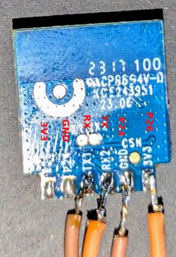
    Ooooh, yes. I only recognized that RX2 marking must be wrong as mentioned in several guides but RX & TX is swapped. First try and success. Thank you

    Image of a blue circuit board with visible markings TX2 RX2. The board has connected wires.
  • #16 21086707
    p.kaczmarek2
    Moderator Smart Home
    No problem, I think that I even did the same back when I first found that strange silkscreen issue. Luckily the module survived.

    Judging by the fact that you are not the first person to have this issue on our forum, I can observe that those incorrectly marked modules must be quite common.

    Added after 18 [seconds]:

    PS: That's why it's good to post photos when asking the question...

    Added after 0 [seconds]:

    PS: That's why it's good to post photos when asking the question...
    Helpful post? Buy me a coffee.
  • ADVERTISEMENT
  • #17 21332287
    fortunatornforty76
    Level 2  
    >>21086597

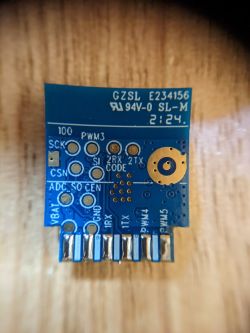
    I have the same WIFI module. It seems impossible but there is an error in the writing on the back side. Using the correct pinout, ignoring the printed text, I was able to flash. You can compare the pinout with online photos of other CB2S. You can even compare ESP02S which has the same pinout and can directly replace CB2S

    WIFI module CB2S with visible pin markings on a blue board.
    Image of a WIFI module with clearly visible pins and markings. Understanding the Aubess FS-02HW Mini Smart Switch: A Detailed Look at Chip CB2S BL2028N

    WIFI module with labeled pins 3V3, GND, RX, TX, P24, P26.
  • #18 21438473
    groove6j
    Level 8  
    The switch flashes and works properly, but compared with the other mini switches, it's temperature is very high at 80-85 degrees reported. Other switches idle at 40-50. I have the PowerSave 1 enabled.
  • #19 21438559
    p.kaczmarek2
    Moderator Smart Home
    Maybe try swapping CB2S with a module from a device with lower temperature?

    This way you will be able to tell what's the reason of the heat - whether it's the WiFi module or the PCB circuit.
    Helpful post? Buy me a coffee.
  • #20 21438592
    groove6j
    Level 8  
    p.kaczmarek2 wrote:
    This way you will be able to tell what's the reason of the heat - whether it's the WiFi module or the PCB circuit.

    Yeah. I have two of these switches and both are hot. I have some spare ESP-02, might try those, because I don't have any spare BK7231N's at hand.
    From the many devices I have flashed, these were the only ones with wrong pinout writings on the board. Maybe the modules cause this issue indeed.
  • #21 21440741
    groove6j
    Level 8  
    The modules despite the wrong pinout labels are fine. The relays seem to get quite hot, even if there is no current passing by. Perhaps they need replacing.

Topic summary

The discussion revolves around the Aubess FS-02HW Mini Smart Switch, which utilizes the CB2S (BL2028N) chip. Users are experiencing difficulties in flashing the device, with some noting issues related to incorrect silkscreen markings on the chip, which can lead to confusion during the flashing process. Several users have attempted various methods to flash the device, including desoldering the chip and using different UART converters, but have encountered problems such as lack of communication and unresponsive outputs. Solutions discussed include ensuring correct wiring, using the appropriate flasher version, and referring to documentation for correct pin configurations. Some users have successfully flashed similar models by following specific guides, while others continue to struggle with the process.
Summary generated by the language model.
ADVERTISEMENT