FAQ
TL;DR: If Cloudcutter fails on WK-US2-TC, use UART: “first read 2MB backup,” then power‑cycle to sync; feed 5V into the AMS1117 input and keep UART logic at 3.3V. [Elektroda, p.kaczmarek2, post #21105876]
Why it matters: This gets you from exploit errors to a reliable wired flash without desoldering.
- Typical workflow: read a 2MB backup, write firmware, power‑cycle once to trigger syncing. [Elektroda, p.kaczmarek2, post #21105876]
- Logic levels: set your USB‑UART adapter to 3.3V; BK7231N UART is 3.3V. [Elektroda, p.kaczmarek2, post #21106137]
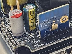
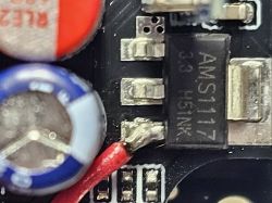
- Powering: supply 5V to AMS1117‑3.3 IN; do not connect adapter’s 3.3V rail. [Elektroda, p.kaczmarek2, post #21106090]
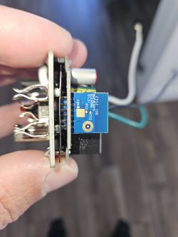
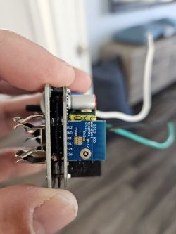
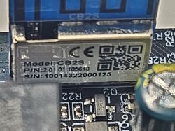
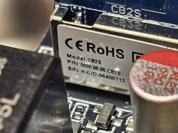
- Module: WK‑US2‑TC/KS‑604S use Tuya CB2S with BK7231N; Tuya data starts at 2,023,424. [Elektroda, 123qweasd1, post #21106142]
- Exploit route: Cloudcutter can be unreliable; wired flashing is recommended fallback. [Elektroda, p.kaczmarek2, post #21105723]
Quick Facts
- Typical workflow: read a 2MB backup, write firmware, power‑cycle once to trigger syncing. [Elektroda, p.kaczmarek2, post #21105876]
- Logic levels: set your USB‑UART adapter to 3.3V; BK7231N UART is 3.3V. [Elektroda, p.kaczmarek2, post #21106137]
- Powering: supply 5V to AMS1117‑3.3 IN; do not connect adapter’s 3.3V rail. [Elektroda, p.kaczmarek2, post #21106090]
- Module: WK‑US2‑TC/KS‑604S use Tuya CB2S with BK7231N; Tuya data starts at 2,023,424. [Elektroda, 123qweasd1, post #21106142]
- Exploit route: Cloudcutter can be unreliable; wired flashing is recommended fallback. [Elektroda, p.kaczmarek2, post #21105723]
How do I flash WK‑US2‑TC when firmware 1.1.17 breaks Cloudcutter?
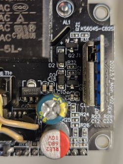
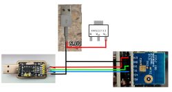
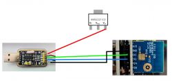
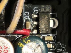
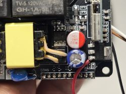
Use UART. Connect GND, RX↔TX, and feed 5V to AMS1117‑3.3 IN. In the flasher, first read a 2MB backup, then write. When prompted, power‑cycle the 5V line once to start syncing. This in‑circuit method works if RX/TX aren’t occupied. [Elektroda, p.kaczmarek2, post #21105876]
What exact wiring should I use with a CH340 USB‑TTL adapter?
Wire GND→GND, adapter RX→device TX, adapter TX→device RX. Provide 5V from the adapter to the AMS1117‑3.3 input. Do not connect the adapter’s 3.3V pin anywhere. Keep data lines at 3.3V logic via the adapter’s jumper. [Elektroda, p.kaczmarek2, post #21106090]
Should the UART adapter be set to 3.3V or 5V for logic levels?
Set logic to 3.3V. The BK7231N serial interface uses 3.3V levels. As the expert notes, “UART levels are in 3.3V.” Power is separate; you still feed 5V only to the AMS1117 input, not to UART pins. [Elektroda, p.kaczmarek2, post #21106137]
Can I flash in‑circuit without removing the board?
Yes, if RX/TX aren’t used by other circuits. Connect 5V to the AMS1117‑3.3 input, wire UART as usual, initiate flashing, then perform a single power cycle when the tool requests it. Start by reading a 2MB backup to verify communication. [Elektroda, p.kaczmarek2, post #21105876]
How do I handle the required power cycle during flashing?
Insert a small inline switch on the 5V feed or unplug/replug the 5V line once when the flasher prompts. This clean power cycle is necessary to start the write/sync phase after your initial 2MB read. [Elektroda, p.kaczmarek2, post #21105876]
Where can I safely pick up GND and UART pins on these boards?
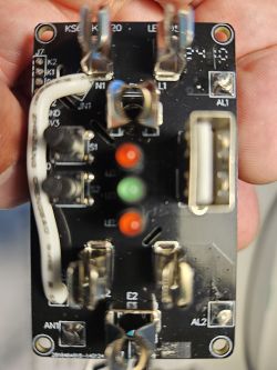
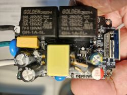
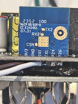
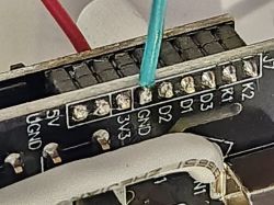
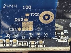
On KS‑604S, users used GND at block J7; on WK‑US2‑TC, GND on the CB2S module worked. Connect adapter RX to module TX and adapter TX to module RX, then verify with a 2MB read. [Elektroda, 123qweasd1, post #21106142]
What mappings did people see after flashing (buttons, relays, LEDs)?
Extracted Tuya config shows P11 button, relays on P26/P8/P6 (plus P7 on 4‑gang), and Wi‑Fi LED on P10. Devices report CB2S (BK7231N), with Tuya section starting at 2,023,424 bytes. Save these details before changes. [Elektroda, 123qweasd1, post #21106142]
What is OpenBeken, in simple terms?
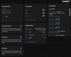
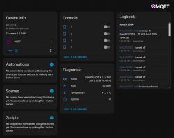
OpenBeken is community firmware that replaces Tuya/BK7231 stock firmware to enable local control and customization on devices like WK‑US2‑TC. If OTA exploits fail, users switch to UART flashing to install it. [Elektroda, 123qweasd1, post #21105683]
What is Tuya, CB2S, and BK7231N?
Tuya is the original IoT platform. CB2S is a Tuya Wi‑Fi module carrying the BK7231N MCU used in these switches. Knowing the module helps you map pins and pick the correct flasher profile. [Elektroda, 123qweasd1, post #21106142]
Why doesn’t Cloudcutter work on my unit?
Exploit reliability varies by firmware build. The maintainer advises treating Cloudcutter as unreliable and switching to wired UART flashing when it fails to trigger on versions like 1.1.17. [Elektroda, p.kaczmarek2, post #21105723]
New Moes revision (Oct 2025): wired flashing no longer syncs. What gives?
Users report that feeding 5V to the AMS1117 input no longer starts sync, and even grounding CEN fails. This revision may block in‑circuit flashing, suggesting off‑circuit access or alternate power injection is needed. [Elektroda, 123qweasd1, post #21711057]
Can I power the board from the adapter’s 3.3V instead of 5V to the LDO?
No. The guidance is explicit: do not connect the adapter’s 3.3V line at all. Provide only 5V to the AMS1117‑3.3 input, and keep UART signals at 3.3V logic. [Elektroda, p.kaczmarek2, post #21106090]
How can I confirm success on KS‑604S and WK‑US2‑TC?
Two successful UART flashes were reported, one per model. Validate by reading the initial 2MB, completing the write after a single power cycle, and confirming GPIO mappings and LED behavior post‑boot. [Elektroda, 123qweasd1, post #21106142]
Where does the Tuya data region start for backup parsing?
The Tuya section begins at byte offset 2,023,424 on these dumps. Keep that number with your backups to make future restores or migrations easier. [Elektroda, 123qweasd1, post #21106142]
What’s the safest minimal procedure to avoid bricking?
- Wire GND, RX↔TX, and 5V to AMS1117‑3.3 IN; set UART logic to 3.3V.
- In BK7231 GUI Flasher, perform a 2MB read and save the backup.
- Start write, then power‑cycle 5V once when prompted to begin syncing. [Elektroda, p.kaczmarek2, post #21105876]
Any tips if the UART method still fails to sync?
Recheck AMS1117 input pin, swap RX/TX, and ensure the adapter stays in 3.3V logic. Try a different adapter cable and a clean 5V source. Newer boards may require off‑circuit access if CEN grounding also fails. [Elektroda, 123qweasd1, post #21711057]


